Tag: OT cyber security

OT security engineering principles

Are there rules an engineer must follow when executing a new project? This week Yacov Haimes passed away at the age of 86 years. Haimes was an American of Iraqi decent and a monument when it comes to risk modeling of what he called systems of systems. His many publications among which his books “Modeling and Managing Interdependent Complex Systems of Systems” (2019) and “Risk Modeling, Assessment, And Management” (2016) provided me with a lot of valuable insights that assisted me to execute and improve quantitative risk assessments in the process industry. He was a man who tried to analyze and formalize the subjects he taught and as such created some “models” that helped me to better understand what I was doing and guide me along the way.

Readers that followed my prior blogs know that I consider automation systems as Systems of Systems (SoS) and have discussed these systems and their interdependencies and interconnectedness (I-I) often in the context of OT security risk. In this blog I like to discuss some of these principles and point to some of the gaps I noticed in methods and standards used for risk assessments conflicting with these principles. To start the topic I introduce a model that is a merger between two methods, on one side the famous 7 habits of Covey and on the other side a system’s development process, and use this model as a reference for the gaps I see. Haimes and Schneiter published this model in a 1996 IEEE publication, I kind of recreated the model in Visio so we can use it as a reference.

A holistic view on system’s engineering Haimes and Schneiter (C) 1996 IEEE

I just pick a few points per habit where I see gaps between the present practice advised by standards of risk engineering / assessment and some practical hurdles. But I like to encourage the reader to study the model in far more detail than I cover in this short blog.

The first Stephen Covey habit is, habit number 1 “Be proactive” and points to the engineering steps that assist us in defining the risk domain boundaries and help us to understand the risk domain itself. When we start a risk analysis we need to understand what we call the “System under Consideration”, the steps linked to habit 1 describe this process. Let’s compare this for four different methods and discuss how these methods implement these steps, I show them above each other in the diagram so the results remain readable.

Four risk methods

The ISO 31000 is a very generic model, that can be used both for quantitative risk assessment as well as qualitative risk assessment. (See for the definitions of risk assessments my previous blog) The NORSOK model is a quantitative risk model used for showing compliance with quantitative risk criteria for human safety and the environment. The IEC/ISA 62443.3.2 model is a generic or potentially a qualitative risk model specifically constructed for cyber security risk as used by the IEC/ISA 62443 standard in general. The CCPS model is a quantitative model for quantitative process safety analysis. It is the 3rd step in a refinement process starting with HAZOP, then LOPA, and if more detail is required than CPQRA.

Where do these four differ if we look at the first two habits of Covey? The proactive part is covered by all methods, though CCPS indicates a focus on scenarios, this is primarily so because the HAZOP covers the identification part in great detail. Never the less for assessing risk we need scenarios.

An important difference between the models rises from habit 2 “Begin with the end”. When we engineer something we need clear criteria, what is the overall objective and when is the result of our efforts (in the case of a risk assessment and risk reduction, the risk) acceptable?

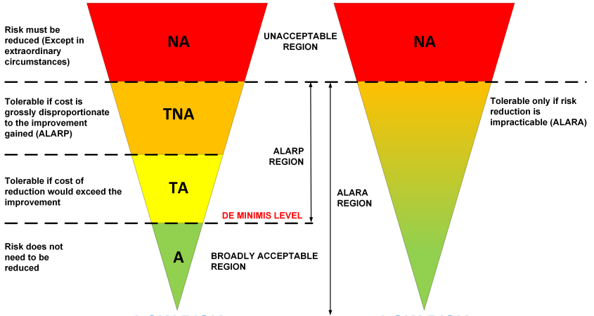
This is the first complexity and strangely enough are these criteria a hot topic between continents, my little question “when is risk acceptable?” is for many Americans an unacceptable question, the issue is their legal system which mixes “acceptability” and “accountability” so they translate this into “when is risk tolerable”. However the problem here is that there are multiple levels for tolerable. European law is as usual diverse, we have countries that follow the ALARP principle (As Low As Reasonably Practical) and we have countries that follow the ALARA principle (As Low As Reasonably Achievable). ALARP has a defined “DE MINIMIS” level, kind of a minimum level where we can say risk is reduced to a level that is considered an acceptable risk reduction by a court of law. Contrary to ALARA where we need to reduce the risk to the level it is no longer practicable, so there is no cost criterium but only a pure technical criterium.

ALARP, ALARA comparison

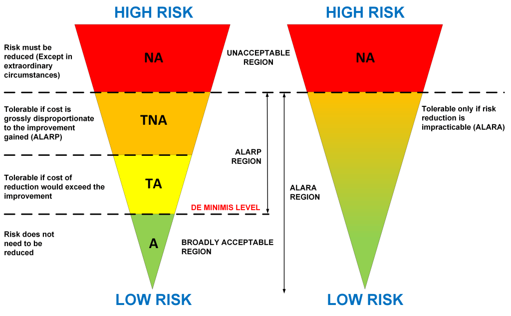
For example the IEC/ISA 62443-3-2 standard compares risk with the tolerable level without defining what that level is. For an ALARA country (e.g. Germany, Netherlands) that level is clearly defined by the law and the IEC / ISA interpretation (stopping further risk reduction at this level) would not be acceptable, for an ALARP country (e.g. UK) the limits and conditions are also well defined but cost related. The risk reduction must go all the way to the DE MINIMUS level if cost would allow it. Which is in cyber security for a chemical plant often the case, this because the cost of a cyber incident – that can cause one or multiple fatalities – in the UK this cost is generally higher than the cost of the cyber security measures that could have prevented it. The cost of a UK fatality is set to approx. 1.5 million pound, actually an American is triple that cost 😊according to the US legal system, the Dutch and Germans (being ALARA) are of course priceless.

So it is important to have clear risk acceptance criteria established and objectives when we start a risk assessment. If we don’t – such as is the case for IEC/ISA 62443.3.2 comparing initial and residual risk with some vaguely defined tolerable risk level – the risk reduction most likely fails a legal test in a court room. ALARP / ALARA are also legal definitions, and cyber security also needs to meet these. Therefore the step risk planning is an essential element of the first NORSOK step and in my opinion should always be the first step, engineering requires a plan towards a goal.

Another very important element according Haines is the I-I (interdependencies, interconnectedness) element. Interconnectedness is covered by IEC/ISA 624433.2 by the zone and conduit diagram, conduits connect zones, though these conduits are not necessarily documented at the level allowing us to identify connections within the zone that can be of relevance for cyber risk (consider e.g. ease of malware propagation within a zone).

Interdependencies are ignored by IEC/ISA 62443. The way to identify these interdependencies is typically conducting a criticality analysis or a Failure Mode and Effect Analysis (FMEA). Interdependencies propagate risk because the consequence of function B might depend on the contribution of function A. A very common interdependency in OT is when we take credit in a safety risk analysis for both a safeguard provided by the SIS (e.g. a SIF) and a safeguard provided by the BPCS (e.g. an alarm), if we need to reduce risk with a factor 10.000, there might be a SIL 3 SIF defined (factor 1000) and the BPCS alarm (factor 10). If a cyber attack can disable one of the two the overall risk reduction fails. Disabling process alarms is relatively easy to do with a bit of ARP poisoning, so from a cyber security point of view we have an important interdependency to consider.

Habit 1 and 2 are very important engineering habits, if we follow the prescriptions taught by Haines we certainly shouldn’t ignore the dependencies when we analyze risk as some methods do today. How about habit 3? This habit is designed to help concentrate efforts toward more important activities, how can I link this to risk assessment?

Especially when we do a quantitative risk assessment vulnerabilities aren’t that important, threats have an event frequency and vulnerabilities are merely the enablers. If we consider risk as a method that wants to look into the future, it is not so important what vulnerability we have today. Vulnerabilities come and go, but the threat is the constant factor. The TTP is as such more important than the vulnerability exploited.

Of course we want to know something about the type of vulnerability, because we need to understand how the vulnerability is exposed in order to model it, but if we yes/no have a log4j vulnerability is not so relevant for the risk. Today’s log4j is tomorrow’s log10k. But it is essential to have an extensive inventory of all the potential threats (TTPs) and how often these TTPs have been used. This information is far more accessible than how often a specific exposed (so exploitable) vulnerability exists. We need to build scenarios and analyze the risk per scenario.

Habit 4 is also of key importance, win-win makes people work together to achieve a common goal. The security consultant’s task might be to find the residual risk for a specific system, but the asset owner typically wants more than a result because risk requires monitoring, risk requires periodic reassessment. The engineering method should support these objectives in order to facilitate the risk management process. Engineering should always consider the various trade-offs there are for the asset owner, budgets are limited.

Habit 5 “Seek first to understand, then to be understood” can be directly linked to the risk communication method and linked to the perspective of the asset owner on risk. So reports shouldn’t be thrown over the wall but discussed and explained, results should be linked to the business. Though this might take considerably more time it is never the less very important.

But not an easy habit to acquire as engineer since we often are kind of nerds with an exclusive focus on “our thing” expecting the world to understand what is clear for us. One of the elements that is very important to share with the asset owner are the various scenarios analyzed. The scenario overview provides a good insight in what threats have been evaluated (typically close to 1000 today, so a sizeable document of bow-ties describing the attack scenarios and their consequences) and the overview allows us to identify gaps between the scenarios assessed and the changing threat landscape.

Habit 6 “Synergize”, is to consider all elements of the risk domain but also their interactions and dependencies. There might be influences from outside the risk domain not considered, never the less these need to be identified another reason why dependencies are very important. Risk propagates in many ways, not necessarily exclusively over a network cable.

Habit 7 “Sharpen the saw”, if there is one discipline where this is important than it is cyber risk. The threat landscape is in continuous movement. New attacks occur, new TTP is developed, and proof of concepts published. Also whenever we model a system, we need to maintain that model, improve it, continuously test it and adjust where needed. Threat analysis / modelling is a continuous process, results need to be challenged, new functions added.

Business managers typically like to develop something and than repeat it as often as possible, however an engineering process is a route where we need to keep an open eye for improvements. Habit 7 warns us against the auto-pilot. Risk analysis without following habit 7 results in a routine that doesn’t deliver appropriate results, one reason why risk analysis is a separate discipline not just following a procedure as it still is for some companies.


There is no relationship between my opinions and references to publications in this blog and the views of my employer in whatever capacity. This blog is written based on my personal opinion and knowledge build up over 43 years of work in this industry. Approximately half of the time working in engineering these automation systems, and half of the time implementing their networks and securing them, and conducting cyber security risk assessments for process installations since 2012.


Author: Sinclair Koelemij

OTcybersecurity web site

Why process safety risk and cyber security risk differ


Abstract

When cyber security risk for process automation systems is estimated I often see references made to process safety risk. This has several reasons:

  • For estimating risk we need likelihood and consequence, the process safety HAZOP and LOPA processes used by plants to estimate process safety risk, identify the consequence of the process scenarios they identify and analyze. These methods also classify the consequence in different categories such as for example finance, process safety, and environment.
  • People expect a cyber security risk score that is similar to the process safety risk score, a score expressed as loss based risk. The idea is that the cyber threat potentially increases the process safety risk and they like to know how much that risk is increased. Or more precisely how high is the likelihood that the process scenario could occur as result of a cyber attack.
  • The maturity of the process safety risk estimation method is much higher than the maturity of cyber security risk estimation methods in use. Not that strange if you consider that the LOPA method is about 20 years old, and the HAZOP method goes back to the end sixties. When reading publications, or even the standards on cyber security risk (e.g. IEC 62443-3-2) this lack of maturity is easily detected. Often qualitative methods are selected, however these methods have several drawbacks which I discuss later.

This blog will discuss some of these differences and immaturities. I’ve done this in previous blogs mainly by comparing what the standards say and what I’ve experienced and learned over the past 8 years as a cyber risk analysis practitioner for process automation systems doing a lot of cyber risk analysis for the chemical, and oil and gas industries. This discussion requires some theory, I will use some every day examples to explain to make it more digestible.


Let us start with a very important picture to explain process safety risk and its use, but also to show how process safety risk differs from cyber security risk.

Process safety FN curve

There are various ways to express risk, the two most used are risk matrices and FN plots / FN curve. FN curves require a quantitative risk assessment method, such as used in process safety risk analysis by for example LOPA. In an FN curve we can show the risk criteria. The boundaries for what we consider acceptable risk and what we consider unacceptable risk. I took a diagram that I found on the Internet where we have a number of process safety scenarios (shown as dots on the blue line) their likelihood of occurrence ( the vertical ax) and in this case the consequence expressed in fatalities when such a consequence can happen (horizontal ax). The diagram is taken from a Hydrogen plant, these plants belong to the most dangerous plants, this is why we see the relative high number of scenarios with a single or multiple fatalities.

Process safety needs to meet regulations / laws that are associated with their plant license. One such “rule” is that the likelihood of “in fence” fatalities must be limited to 1 every 1000 years (1.00E-3) If we look at the risk tolerance line (RED) in the diagram we see that what is considered tolerable and intolerable is exactly at the point where the line crosses the 1.00E-03 event frequency (likelihood). Another often used limit is the 1.00E-04 frequency for the limit used as acceptable risk, risk not further addressed.

How does process safety determine this likelihood for a specific process scenario? In process safety we have several structured methods for identifying hazards. One of them is the Hazard and Operability study, in short the HAZOP. In a hazop we analyze, for a specific part of the process, if specific conditions can occur. For example we can take the flow through an industrial furnace and analyze if we can have a high flow, no flow, maybe reverse flow. If such a condition is possible we look at the cause of this (the initiating event), perhaps no flow because a pump fails. If we have established the cause (the initiating event) we consider what would be the process consequence. Well possibly the furnace tubing will be damaged, the feed material would leak into the furnace and an explosion might occur. This is what is called the process consequence. This explosion has an impact on safety, one or multiple field operators might be in the neighborhood and killed by the explosion. There will also be a financial impact, and possibly an environmental impact. A hazop is a multi-month process where a team of specialists goes step by step through all units of the installation and considers all possibilities and ways how to mitigate this hazard. This results in a report with all analysis results documented and classified. Hazops are periodically reviewed in a plant to account for possible changes, this we call the validity period of the analysis.

However we don’t have yet a likelihood expressed as an event frequency such as used in the FN curve. This is where the LOPA method comes in. LOPA has tables for all typical initiating events (causes), so the event frequency for the failure of a pump has a specific value (for example 1E-01, once every 10 years). How were these tables created? Primarily based on statistical experience. These tables have been published, but can also differ between companies. It is not so that a poly propylene factory of company A uses by default the same tables as a poly propylene factory of company B. All use the same principles, but small differences can occur.

In the example we have a failing pump with an initiating frequency of once every 10 years and a process consequence that could result in a single fatality. But we also know that our target for single fatalities should be once per 1000 years or better. So we have to reduce this event frequency of 1E-01 with at least a factor 100 to get to once per 1000 years.

This is why we have protection layers, we are looking for one or more protection layers that offer us a factor one hundred extra protection. One of these protection layers can be the safety system, for example a safety controller that detects the no flow condition by measuring the flow and shuts down the furnace to a safe state using a safety valve. How much “credit” can we take for this shutdown action? This depends on the safety integrity level (SIL) of the safety instrumented function (SIF) we designed. This SIF is more than the safety controller where the logic resides, the SIF includes all components necessary to complete the shutdown function, so will include transmitters that measure the flow and safety valves that close any feed lines and bring other parts of the process into a safe condition.

We assign a SIL to the SIF. We typically (SIL 4 does exist) have 3 safety integrity levels: SIL 1, 2, and 3. According to LOPA a SIL 1 SIF gives us a reduction of a factor 10, SIL 2 will reduce the event frequency by a factor 100, and SIL 3 by a factor 1000.

How do we estimate if a SIF meets the requirements for SIL 1, 2, or 3? This requires us to estimate the average probability of failure on demand for the SIF. This estimation makes use of mean time between failure of the various components of the SIF and the test frequency of these components. For this blog I skip this part of the theory, we don’t have to go into that level of detail. High level we estimate what we call the probability of failure on demand for the protection layer (the SIF). In our example we need a SIF with a SIL 2 rating, a protection level relatively easy to create.

In the FN curve you can also see process scenarios that require more than a factor 100, for example a factor 1000 like in a SIL 3 SIF. This requires a lot more, both from the reliability of the safety controller as well as from the other components. Maybe a single transmitter is not reliable enough anymore and we need some 2oo3 (two out of three) configuration to have a reliable measurement. Never the less the principle is the same, we have some initiating event, we have one or more protection layers capable of reducing the event frequency with a specific factor. These protection layers can be a safety system (like in my example), but also some physical device (e.g. pressure relief valve), an alarm from the control system, an operator action, a periodic preventive maintenance activity, etc. LOPA gives each of these protection layers what is called a credit factor, a factor with which we can reduce the event frequency when the protection layer is present.

So far the theory of process safety risk,. One topic I avoided discussing here is the part where we estimate the probability of failure on demand (PFDavg) for a protection layer. But it has some relevance for cyber risk estimates. If we would go into more detail and discuss these formulas to estimate the effectiveness / reliability of the protection layer we see that the formulas for estimating PFDavg we depend on what is called the demand rate. The demand rate is the frequency which we expect the protection layer will needs to act.

The standard (IEC 61511) makes a difference between what is called low-demand rate and high / continuous demand rate. The LOPA process is based upon the low demand-rate formulas, the tables don’t work for high / continuous demand rate. This is an important point to notice when we start a quantitative cyber risk analysis because the demand rate of a cyber protection layer is by default a high / continuous demand rate type of protection layer. This difference impacts the event frequency scale and as such the likelihood scale. So if we were to estimate cyber risk in a similar manner as we estimated process safety risk we end up with different likelihood scales. I will discuss this later.


A few important points to note from above discussion:

  • Process safety risk is based on randomly occurring events, events based on things going wrong by accident, such as a pump failure, a leaking seal, an operator error, etc.
  • The likelihood scale of process safety risk has a “legal” meaning, plants need to meet these requirements. As such a consolidated process safety and cyber security risk score is not relevant and because of estimation differences not even possible.
  • When we estimate cyber security risk, the process safety risk is only one element. With regard to safety impact the identified safety hazards will most likely be as complete as possible, but the financial impact will not be complete because financial impact might also result from scenarios that do not impact process operations but might impact the business. The process safety hazop or LOPA does not generally address cyber security scenarios for systems that have no potential process impact, for example a historian or metering function.
  • The IEC 62443 standard tries to introduce the concept of “essential” functions and ties these functions directly to the control and safety functions. However plants and automation functions have many essential tasks not directly related to the control and safety functions, for example various logistic functions. The automation function contains all functions connected to level 0, level 1, level 2, level 3, and demilitarized zone. When we do a risk analysis these systems should be included, not just the control and safety elements. The problem that a ship cannot dock to a jetty also has significant cost to consider in a cyber risk analysis.
  • Some people suggest that cyber security provides process safety (or worse the wider safety is even suggested.) This is not true, process safety is provided by the safety systems. The various protection layers in place. Cyber security is an important condition for these functions to do their task, but not more as a condition. The Secret Service protects the president of the US against various threats, but it is the president of the US that governs the country – not the Secret Service by enabling the president to do his task.

Where does cyber security risk differ from process safety risk? Well first of all they have different likelihood scales. Process safety risk is based on random events, cyber security risk is based on intentional events.

Then there is the difference that a process safety protection layer always offers full protection when it is executed, many cyber security protection layers don’t. We can implement antivirus as a first protection layer, application white listing as a 2nd protection layer, they both would do their thing but still the attacker can slip through.

Then there is the difference that a cyber security protection layer is almost continually “challenged”, where in process safety the low demand rate is most often applied, which sets the maximum demand rate to once a year.


If we would look toward cyber security risk in the same way as LOPA does toward process safety risk, we could define various events with their initiating event frequency. For example we could suggest an event such as a malware infection to occur bi-annually. We could assign protection layers against this, for example anti-virus and assign this protection layer a probability of failure on demand (risk reduction factor), so a probability on a false negative or false-positive. If we have an initiating event (the malware infection) with a certain frequency and a protection layer (antivirus) with a specific reduction factor we can estimate a mitigated event frequency (of course taking high demand rate into account).

We can also consider multiple protection layers (e.g. antivirus and application white listing) and arrive at a frequency representing the residual risk after applying the two protection layers. Given various risk factors and parameters to enter the system specific elements and given a program that evaluates the hundreds of attack scenarios, we can arrive at a residual risk for one or hundreds of attack scenarios.

Such methods are followed today, not only by the company I work for but also by several other commercial and non-commercial entities. Is it better or worse than a qualitative risk analysis (the alternative)? I personally believe it is better because the method allows to take multiple protection layers into account. Is it actuarial type of risk, no it is not. But the subjectivity of a qualitative assessment has been removed because of the many factors determining the end result and we have risk now as residual risk based upon taking multiple countermeasures into account.

Still there is another difference between process safety and cyber security risk not accounted for. This is the threat actor in combination with his/her intentions. In process safety we don’t have a threat actor, all is accidental. But in cyber security risk we do have a threat actor and this agent is a factor that influences the initiating event frequency of an attack scenario.

The target attractiveness of facilities differ for different threat actors. A nation state threat actor with all its capabilities is not likely to attack the local chocolate cookie factory, but might show interest in an important pipeline. Different threat actors mean different attack scenarios to include but also influence the initiating event frequency it self. Where non-targeted attacks show a certain randomness of occurrence, a targeted attack doesn’t show this randomness.

We might estimate a likelihood for a certain threat actor to achieve a specific objective for the moment that the attack takes place, but this start moment is not necessarily random. Different factors influence this, so to express cyber risk on a similar event frequency scale as process safety risk is not possible. Cyber security risk is not based on the randomness of the event frequencies. If there is a political friction between Russia and Ukraine, the amount of cyber attacks occurring and skills applied is much bigger than in times without such a conflict.

Therefore cyber security risk and process safety risk cannot be compared. Though the cyber threat certainly increases the process safety risk (both initiating event frequency can be higher and the protection layer might not deliver the level of reliability expected), we can not express this rise in process safety risk level because of the differences discussed above. Process safety risk and cyber security risk are two different things and should be approached differently. Cyber security has this “Secret Service” role, and process safety this “US president” role. We can estimate the cyber security risk that this “Secret Service” role will fail and the US government role is made to do bad things, but that is an entirely different risk than that the US government role will fail. It can fail even when the “Secret Service” role is fully active and doing its job. Therefore cyber security risk has no relation with process safety risk, they are two entirely different risks. The safety protection layers provide process safety (resilience against accidental failure), the cyber security protection layers provide resilience against an intentional and malicious cyber attack.


There is no relationship between my opinions and references to publications in this blog and the views of my employer in whatever capacity. This blog is written based on my personal opinion and knowledge build up over 43 years of work in this industry. Approximately half of the time working in engineering these automation systems, and half of the time implementing their networks and securing them, and conducting cyber security risk assessments for process installations since 2012.


Author: Sinclair Koelemij

OTcybersecurity web site

Are Power Transformers hackable?

There is a revived attention for supply chain attacks after the seize of a Chinese transformer in the port of Houston. While on its way to a US power transmission company – Western Area Power Administration (WAPA) – the 226 ton transformer was rerouted to Sandia National Laboratories in Albuquerque New Mexico for inspection on possible malicious implants.

The sudden inspection happens more or less at the same time that the US government issued a presidential directive aiming for white listing vendors allowed to supply solutions for the US power grid, and excluding others to do so. So my curiosity is raised and additionally triggered by the Wall Street Journal claim that transformers do not contain software-based control systems and are passive devices. Is this really true in 2020? So the question is, are power transformers “hackable” or must we see the inspection exclusively as a step in increasing trade restrictions.


Before looking into potential cyber security hazards related to the transformer, let’s first look at some history of supply chain “attacks” relevant for industrial control systems (ICS). I focus here on supply chain attacks using hardware products because in the area of software products, Trojan horses are quite common.

Many supply chain attacks in the industry are based on having purchased counterfeit products. Frequently resulting in dangerous situations, but generally driven by economic motives and not so much by a malicious intent to damage the production installation. Some examples of counterfeits are:

  • Transmitters – We have seen counterfeit transmitters that didn’t qualify for the intrinsic safety transmitter zone qualifications specified by the genuine product sheet. And as such creating a dangerous potential for explosions in a plant when these products would be installed in zone 1 and zone 0 areas with a potential for the presence of explosive gases.
  • Valves – We have seen counterfeit valves, where mechanical specifications didn’t meet the spec sheet of the genuine product. This might lead to the rupture of the valve resulting in a loss of containment with potential dangerous consequences.
  • Network equipment – On the electronic front we have seen counterfeit Cisco network equipment that could be used to create a potential backdoor in the network.

However it seems that the “attack” here is more an exploit of the asset owner’s vulnerability for low prices (even if they sound ridiculously low), in combination with highly motivated companies trying to earn some fast money, than an intentional and targeted attack on the asset integrity of an installation.

That companies selling these products are often found in Asia, with China as the absolute leader according to reports, is probably caused by a different view / attitude toward patents, standards and intellectual property in a fast growing region and additionally China’s economic size. Not necessarily a plot against an arrogant Western world enemy.

The most spectacular example of such an incident is where counterfeit Cisco equipment ended up in the military networks of the US. But as far as I know, it was also in this case never shown that the equipment’s functionality was maliciously altered. Main problem was a higher failure rate caused by low manufacturing standards, potentially impacting the networks reliability. Never the less also here a security incident because of the potential for malicious functionality.

Also proven malicious incidents have occurred, for instance in China, where computer equipment was sold with already pre-installed malware. Malware not detectable by antivirus engines. So the option to attack industrial control systems through the supply chain certainly exist, but as far as I am aware never succeeded.

But there is always the potential that functionality is maliciously altered, so we need to see above incidents as security breaches and consider them to be a serious cyber security hazard we need to address. Additionally power transformers are quite different from the hardware discussed above, so a supply chain attack on US power grid using power transformers is a different analysis. If it would happen and was detected it would mean end of business for the supplier, so stakes are high and chances that it happens are low. Let’s look now at the case of the power transformer.


For many people, a transformer might not look like an intelligent device. But in today’s world everything in the OT world becomes smart (not excluding the possibility we ourselves might be the exception), so we also have smart power transformers today. Partially surfing on the waves of the smart hype, but also adding new functions that can be targeted.

Of course I have no information on the specifications of the WAPA transformer, but it is a new transformer so probably making use of today’s technology. Since seizing a transformer is not a small thing, transformers used in the power transmission world are designed to carry 345 kilo volts or more and can weigh as much as 410 tons (820.000 lb in the non-metric world), there must be a good reason to do so.

One of the reasons is of course that it is very critical and expensive equipment (can be $5.000.000+) and is built specifically for the asset owner. If it would fail and be damaged, replacement would take a long time. So this equipment must not only be secure, but also be very reliable. So worth an inspection from different viewpoints.

What would be the possibilities for an attacker to use such a huge lump of metal for executing a devious attack on a power grid. Is it really possible, are there scenarios to do so?

Since there are many different types of power transformers, I need to make a choice and decided to focus on what are called conservator transformers, these transformers have some special features and require some active control to operate. Looking at OT security from a risk perspective, I am more interested in if a feasible attack scenario exists – are there exposed vulnerabilities to attack, what would be the threat action – then in a specific technical vulnerability in the equipment or software that make it happen today. To get a picture of what a modern power transformer looks like, the following demo you can play with (demo).

Look for instance at the Settings tab and select the tap position table from where we can control or at minimum monitor the onload tap changes (OLTC). Tap changers select variable turn ratios to either increase or decrease the turn ratio to regulate the output voltage for variations on the input side. Another interesting selection you find when selecting the Home icon, leading you directly to the Buchholz safety relay. Also look at the interface protocol Goose, I would say it all looks very smart.

I hope everyone realizes from this little web demo, that what is frequently called a big lump of dumb metal might actually be very smart and containing a lot more than a view sensors to measure temperature and level as the Wall Street Journal suggests. Like I said I don’t know WAPA’s specification, so maybe they really ordered a big lump of dumb metal but typically when buying new equipment companies look ahead and adopt the new technologies available.

Let’s look in a bit more detail to the components of the conservator power transformer, being a safety function the Buchholz relay is always a good point to start if we want to break something. The relay is trying to prevent something bad from happening, what is this and how does this relay counter this, can we interfere?

A power transformer is filled with insulating oil to insulate and serve as a coolant between the windings. The Buchholz relay connects between the overhead conservator (a tank with insulating oil) and the main oil tank of the transformer body. If a transformer fails, or is overloaded this causes extra heat, heated insulating oil forms gas and the trapped gas presses the insulating oil level further down (driving it into the conservator tank passing the Buchholz relay function) so reducing the insulation between the windings. The lower level could cause an arc, speeding up the process and causing more gas pressure, pressing the insulating oil even more away and exposing the windings.

It is the Buchholz relay’s task to detect this and operate a circuit breaker to isolate the transformer before the fault causes additional damage. If the relay wouldn’t do its task quick enough the transformer windings might be damaged causing a long outage for repair. In principal Buchholz relays, as I know them, are mechanical devices working with float switches to initiate an alarm and the action. So I assume there is not much to tamper with from a cyber point of view.

How about the tap changer? This looks more promising, specifically an on load tap changer (OLTC). There are various interesting scenarios here, can we make step changes that impact the grid? When two or more power transformers work in parallel, can we create out-of-step situations between the different phases by causing differences in operation time?

An essential requirement for all methods of tap changing under load is that circuit continuity must be maintained throughout the tap stepping operation. So we need a make-before-break principle of operation, which causes at least momentary, that a connection is made simultaneously to two adjacent taps on the transformer. This results in a circulating current between these two taps. To limit this current, an impedance in the form of either resistance or inductive reactance is required. If not limited the circulating current would be a short-circuit between taps. Thus time also plays a role. Voltage change between taps is a design characteristic of the transformer, this is normally small approximately 1.25% of the nominal voltage. So if we want to do something bad, we need to make a bigger step than expected. The range seems to be somewhere between +2% and -16% in 18 steps, so quite a jump is possible if we can increase the step size.

To make it a bit more complex, a transformer can be designed with two tap changers one for in phase changes and one for out of phase changes, this also might provide us with some options to cause trouble.

So plenty of ingredients seem to be available, we need to do things in a certain sequence, we need to do it within a certain time, and we need to limit the change to prevent voltage disturbances. Step changers use a motor drive, and motor drives are controlled by motor drive units, so it looks like we have an OT function. Again a bit larger attack surface than a few sensors and a lump of metal would provide us. And then of course we saw Goose in the demo, a protocol with issues, and we have the IEDs that control all this and provide protection, a wider scope to investigate and secure but not part of the power transformer.

Is this all going to happen? I don’t think so, the Chinese company making the transformers is a business, and a very big one. If they would be caught tampering with the power transformers than that is bad for business. Can they intentionally leave some vulnerabilities in the system, theoretically yes but since multiple parties (the delivery contains also non-Chinese parts) are involved it is not likely to happen. But I have seen enough food for a more detailed analysis and inspection to find it very acceptable that also power transformers are assessed for their OT security posture when used in critical infrastructure.

So on the question are power transformers hackable, my vote would be yes. On the question will Sandia find any malicious tampering, my vote would be no. Good to run an inspection but bad to create so much fuss around it.


There is no relationship between my opinions and publications in this blog and the views of my employer in whatever capacity.


Sinclair Koelemij

The Purdue Reference Model outdated or up-to-date?


Is the Purdue Reference Model (PRM) outmoded? If I listen to the Industrial Internet of Things (IIoT) community, I would almost believe so. IIoT requires connectivity to the raw data of the field devices and our present architectures don’t offer this in an easy and secure way. So let’s look in a bit more detail to the PRM and the IIoT requirements, to see if they really conflict or can coexist side by side?


I start the discussion with the Purdue Reference Model, developed in the late 80’s. Developed in a time that big data was anything above 256 Mb and the Internet was still in its early years, a network primarily used by and for university students. PRM’s main objective was creating a hierarchical model for manufacturing automation, what was called computer integrated manufacturing (CIM) in those days. If we see the model as it was initially published we note a few things:

  • The model has nothing to do with a network, or security. There are no firewalls, there is no DMZ.
  • There is an operator console at level 1. Maybe a surprise for people who started to work in automation in the last 20 years, but in those days quite normal.
  • Level 4 has been split in a level 4A and a level 4B, to segment functions that directly interact with the automation layers and functions requiring no direct interface.
  • There is no level 0, the Process layer is what it is a bunch of pipes, pumps, vessels and some clever stuff.

Almost a decade later we had ANSI / ISA-95 that took the work of the Purdue university and extended it with some new ideas and created an international standard that became very influential for ICS design. It was the ANSI / ISA-95 standard that named the Process level, level 0. But in those days level 0 was still the physical production equipment. The ISA-95 standard says following on level 2, level 1, and level 0 : ” Level 0 indicates the process, usually the manufacturing or production process. Level 1 indicates manual sensing, sensors, and actuators used to monitor and manipulate the process. Level 2 indicates the control activities, either manual or automated, that keeps the process stable or under control.” So level 0 is the physical production equipment, and level 1 includes the sensors and actuators. It was many years later that people started using level 0 for the field equipment and their networks, all new developments with the rise of Foundation Fieldbus, Profibus, the HART protocol, but never part of the standard. It was probably the ISA 99 standard that introduced a new layer between level 4 and level 3, the DMZ. It was the vendor community that started giving it a level name, level 3.5. But level 3.5 has never been a functional level, it was an interface between two trust zones for adding security. Though often the way it was implemented contributed little to security, but it was a nice feeling to say we have a demilitarized zone between the corporate network and the control network. So far the history of the Purdue Reference Model and ISA-95 and their contribution to the levels. Now lets have a look at how a typical industrial control system (ICS) looks without immediately using names for levels.


From a functional viewpoint we can split a traditional ICS architecture in 5 main parts:

  • Production management system, which task it is to control the automation functions. Typical domain of the DCS and SCADA systems. But also compressor control (CCS), power management systems (PMS) and the motor control center (MCC) reside here. basically everything that takes care of the direct control of the production process. And of course all these systems interact with each other using a wide range of protocols, many of them with security short comings;
  • Operations management system, which task it is to optimize the production process, but also to monitor and diagnose the process equipment (for example machine monitoring functions such as vibration monitoring), and various management functions such as asset management, accounting and reconciliation functions to monitor the mass balance of process units, and emission monitoring systems to meet environmental regulations;
  • Information systems is the third category, these systems collect raw data and transform it into information to be used for historical trends or to feed other systems with information. The objective here is to transform the raw data into information and ultimately information into knowledge. The data samples stored are normally one minute snapshots, hourly averages, shift averages, daily averages, etc. An other example of an information system is custody metering system (CMS) for measuring product transfer for custody purposes.
  • The last domain of the ICS is the Application domain, for example for advanced process control (APC) applications, traditionally performing advisory functions. But overtime the complexity of running an production processes grew, response to changes in the process became more important so advisory functions were taking over the task of the process operator immediately changing the setpoints using setpoint control or controlling the valve with direct digital control functions. There are plants today that if APC would fail, the production is no longer profitable or can’t reach the required product quality levels.
  • Finally there is the Business domain, generally not part of the ICS. in the business domain we mange for example the feed stock and products to produce. It is the decision domain.
Functional model of a chemical plant or refinery

The production management systems are shown in the light blue color, the operations management, information management, and application systems in the light purple color. The model seems to comply with the models of the ANSI / ISA-95 standard. However this model is far from perfect, because an operations management function as vibration monitoring, or corrosion monitoring also have sensors that connect to the physical system. And an asset management system requires information from the field equipment. If we consider a metering system, also part of the information function, it is actually a combination of a physical system and sensors.


And then of course we have all the issues around vendor support obligations. Asset owners expect systems with a very high level of reliability, vendors have to offer this level of reliability in a challenging real-time environment by testing and validating their systems and changes rigorously. Than there is nothing worse than suddenly having to integrate with the unknown, a 3rd party solution. As a result we see systems that have a level 2 function connected to level 3, in principle exposing a critical system more and making the functionality rely on more components so reducing reliability.


So many conflicts in the model, still it has been used for over 20 years, and it still helps us to guide us in securing systems today. If we take the same model and add some basic access security controls we get the following:

At high level this represents the architecture in use today, in smaller systems the firewall between level 2 and 3 might miss, some asset owners might prefer a DMZ with two firewalls (from different vendors to enforce diversity), the level 4A hosts those functions that interface with the control network and generally different policies are enforced for these systems than required at level 4B. For example asset owners might enforce the use of desktop clients, might limit Internet access for these clients, might restrict email to internal email only, etc. All to reduce the chance on compromising the ICS security.


Despite that the reference model is not supporting all of the new functions we have in plants today – for example I didn’t discuss wireless, virtualization, and system integration topics at level 2 – the reference model still helps structure the ICS. Is it impossible to add the IIoT function to this model? Let’s have a look at what IIoT requires?


In an IIoT environment we have a three level architecture:

  • The edge tier – The edge tier is for our discussion the most important, this is where the interface is created with the sensors and actuators. Sometimes existing sensors / actuators, but also new sensors and actuators.
  • The platform tier – The platform tier processes and transforms the data and controls the direction of the data flow. So from that point also of importance for the security of the ICS.
  • The enterprise tier – This tier hosts the application and business logic that needs to provide the value. It is external to the ICS, so as long as we have a secure end to end connection between the platform tier and the enterprise tier ICS security needs to trust that the systems and data in this tier are properly secured.

The question is can we reconcile these two architectures? The answer seems to be what is called the gateway-mediated edge. This is a device that aggregates and controls the data flows from all the sensors and actuators providing a single point of connection to the enterprise tier. This type of device also performs the necessary translation for communicating with the different protocols used in ICS. The benefits of such a gateway device is the scalability of the solution together with controlling the entry and exit of the data flows from a single controllable point. In this model some of the data processing is kept local, close to the edge, allowing controlled interfaces with different data sources such as Foundation Field Bus, Profibus, and HART enabled field equipment. To implement such an interface device doesn’t require to change the Purdue reference model in my opinion, it can make use of the same functional architecture. Additionally new developments such as the APL (Advanced Physical Layer) technology, the technology that will remove the I/O layer as we know it today, will fully align with this concept.


So I am far from convinced that we need a new model, also today the model doesn’t reflect all the data flows required by today’s functions. The very clear boundaries we used to have, have disappeared with the introduction of new technologies such as virtualization and wireless sensor networks. Centralized process computer systems of the 70s, have disappeared becoming decentralized over the last 30 years and are now moving back into centralized data centers where hardware and software have lose ties. Today these data centers are primarily onsite, but over time confidence will grow and larger chunks of the system will move to the cloud.

Despite all these technology changes, the hierarchical structure of the functions hasn’t change that much. It is the physical location of the functions that changes, undoubtedly demanding a different approach to cyber security. It are the cyber security standards of today that are dated on the day they are released. The PRM was never about security or networking, it is a hierarchical functional model for the relationship between functions which is as relevant today as it was 30 years ago.

We have a world of functional layers, and between these layers data is exchanged, so we have boundaries to protect. As long as we have bi-directional control over the data flows between the functional layers and keep control over where the data resides, we protect the overall function. If there is something we need to change it are the security standards, not the Purdue reference model. But we need to be careful with the security of these gateways as the recent OSI PI security risk has learned us.


There is no relationship between my opinions and publications in this blog and the views of my employer in whatever capacity.


Sinclair Koelemij

TRISIS revisited


For this blog I like to go back in time, to 2017 the year of the TRISIS attack against a chemical plant in Saudi Arabia. I don’t want to discuss the method of the attack (this has been done excellently in several reports) but want to focus on the potential consequences of the attack because I noticed that the actual threat is underestimated by many.

The subject of this blog was triggered after reading Joe Weiss’ blog on the US presidential executive order and noticing that some claims were made in the blog that are incorrect in my opinion. After checking what the Dragos report on TRISIS wrote on the subject, and noticing a similar underestimation of the dangers I decided to write this blog. Let’s start with summing up some statements made in Joe’s blog and the Dragos report that I like to challenge.


I start with quoting the part of Joe’s blog that starts with the sentence: “However, there has been little written about the DCS that would also have to be compromised. Compromising the process sensors feeding the SIS and BPCS could have led to the same goal without the complexity of compromising both the BPCS and SIS controller logic and the operator displays.” The color high lights are mine to emphasize the part I like to discuss.


The sentence seems to suggest (“also have to be compromised”) that the attacker would ultimately also have to attack the BPCS to be effective in an attempt to cause physical damage to the plant. For just tripping the plant by activating a shutdown action the attacker would not need to invest in the complexity of the TRISIS attack. Once gaining access to the control system at the level the attackers did, tens of easier to realize attack scenarios were available if only a shutdown was intended. The assumption that the attacker needs the BPCS and SIS together to cause physical damage is not correct, the SIS can cause physical damage to the plant all by it self. I will explain this later with a for safety engineers well known example of an emergency shutdown of a compressor.


Next I like to quote some conclusions in the (excellent) Dragos report on TRISIS. It starts at page 18 with:

Could This Attack Lead to Loss of Life?

Yes. BUT, not easily nor likely directly. Just because a safety system’s security is compromised does not mean it’s safety function is. A system can still fail-safe, and it has performed its function. However, TRISIS has the capability to change the logic on the final control element and thus could reasonably be leveraged to change set points that would be required for keeping the process in a safe condition. TRISIS would likely not directly lead to an unsafe condition but through its modifying of a system could deny the intended safety functionality when it is needed. Dragos has no intelligence to support any such event occurred in the victim environment to compromise safety when it was needed.


The conclusion that the attack could not likely lead to the loss of life, is in my opinion not a correct conclusion and shows the same underestimation as made by Joe. As far as I am aware the part of the modified logic has never been published (hopefully someone did analyze) so the scenario I am going to sketch is just guessing a potential objective. It is what is called a cyber security hazard, it could have occurred under the right conditions for many production systems including the one in Saudi Arabia. So let’s start with explaining how shutdown mechanisms in combination with safety instrumented systems (SIS) work, and why some of the cyber security hazards related to SIS can actually lead to significant physical damage and potential loss of life.


A SIS has different functions like I explained in my earlier blogs. A little bit simplified summary, there is a preventative protection layer the Emergency Shutdown System (ESD) and there is a mitigative layer, e.g. the Fire & Gas system detecting fire or gas release and activating actions to extinguish fires and to alert for toxic gases. For our discussion I focus on the ESD function, but interesting scenarios also exist for F&G.

The purpose of the ESD system is to monitor process safety parameters and initiate a shutdown of the process system and/or the utilities if these parameters deviate from normal conditions. A shutdown function is a sequence of actions, opening valves, closing valves, stopping pumps and compressors, routing gases to the flare, etc. These actions need to be done in a certain sequence and within a certain time window, if someone has access to this logic and modifies the logic this can have very serious consequences. I almost would say, it always has very serious consequences because the plant contains a huge amount of energy (pressure, temperatures, rotational speed, product flow) that needs to be brought to a safe (de-energized) state in a very short amount of time, releasing incredible powers. If an attacker is capable of tampering with this shutdown process serious accidents will occur.


Let’s discuss this scenario in more detail in the context of a centrifugal compressor, most plants have multiple so always an interesting target for the “OT certified” threat actor. Centrifugal compressors increase the kinetic energy of for example a gas into a pressure so a gas flow through pipelines is created either to transfer a product through the various stages of the production process or perhaps to create energy for opening / closing pneumatic driven valves.

Transient operations, for example the start-up and shutdown of process equipment, always have dangers that need to be addressed. An emergency shutdown because there occurred in the plant a condition that demanded the SIS to transfer the plant to a safe state, is such a transient operation. But in this case unplanned and in principle fully automated, no process operator to guard the process and correct where needed. The human factor is not considered a very reliable factor in functional safety and is often just too slow. SIS on the other hand is reliable, the redundancy and the continuous diagnostic checks all warrant a very low failure on demand probability for SIL 2 and SIL 3 installations. They are designed to perform when needed, no excuses allowed. But this is only so if the program logic is not tampered with, the sequence of actions must be performed as designed and is systematically tested after each change.

Compressors are controlled by compressor control systems (CCS), one of the many sub-systems in an ICS. The main task of a compressor control system is anti surge control. The surge phenomenon in a centrifugal compressor is a complete breakdown and reversal of the flow through the compressor. A surge causes physical damage to the compressor and pipelines because of the huge forces released if a surge occurs. Depending on the gas this can also lead to explosions and loss of containment.

An anti surge controller of the CCS continuously calculates the surge limit (which is dynamic) and controls the compressor operation to stay away from this point of danger. This all works fine during normal operation, however when an emergency shutdown occurs the basic anti surge control provided by the CCS has shown to be insufficient to prevent a surge. In order to improve the response and prevent a surge, the process engineer has two design options called a hot bypass method or a cold bypass method recycling the gas to allow for a more gradual shutdown. The hot bypass is mostly used because of its closeness to the compressor which results into a more direct response. Such a hot bypass method requires to open some valves to feed the gas back to the compressor, this action is implemented as a task of the ESD function. The quantity of gas that can be recycled has a limit, so it is not just opening the bypass valve to 100% but opening it with the right amount. Errors in this process or a too slow reaction would easily result into a surge, damaging the compressor, potentially rupturing connected pipes, causing loss of containment, perhaps resulting in fire and explosions, and potentially resulting in casualties and a long production stop with high repair cost.


All of this is under control of the logic solver application part of the SIS. If the TRISIS attacker’s would have succeeded into loading altered application logic, they would have been capable of causing physical damage to the production installation, damage that could have caused loss of life.

So my conclusion differs a bit, an attack on a SIS can lead to physical damage when the logic is altered, which can result in loss of life. A few changes in the logic and the initiation of the shutdown action would have been enough to accomplish this.


This is just one example of a cyber security hazard in a plant, multiple examples exist showing that the SIS by itself can cause serious incidents. But this blog is not supposed to be a training for certified OT cyber terrorist so I keep it with this for safety engineers well known example.

Proper cyber security requires proper cyber security hazard identification and hazard risk analysis. This has too little focus and is sometimes executed at a level of detail insufficient to identify the real risks in a plant.

I don’t want to criticize the work of others, but do want to emphasize that OT security is a specialism not a variation on IT security. ISA published a book “Security PHA Review” written by Edwar Marsazal and Jim MgClone which addresses the subject of secure safety systems in a for me far too simplified manner by basically focusing on an analysis / review of the process safety hazop sheet to identify cyber related hazards.

The process safety hazop doesn’t contain the level of detail required for a proper analysis, neither does the process safety hazop process assume malicious intent. One valve may fail, but multiple valves at the same time in a specific sequence is very unlikely and not considered. While these options are fully open to the threat actor with a plan.

Proper risk analysis starts with identifying the systems and sub-systems of an ICS, than identifying cyber security hazards in these systems, identifying which functional deviations can result from these hazards, and than translate how these functional deviations can impact the production system. That is much more than a review of a process hazop sheet on “hackable” safeguards and causes. That type of security risk analysis requires OT security specialists with a detailed knowledge on how these systems work, what their functional tasks are, and the imagination and dose of badness to manipulate these systems in a way that is beneficial for an attacker .

Sinclair Koelemij