The Ukraine crisis will almost certainly raise the cyber security risk for the of rest Europe. The sanctions imposed on Russia demand an increased awareness and defense effort for securing the OT systems. These sanctions will hurt and shall undoubtedly become an incentive for an organized revenge from very capable threat actors. What could be more effective for them than cyberattacks at a safe distance.
I think all energy-related installations such as for example port terminals, pipelines, gas distribution, and possibly power will have to raise their level of alertness. Until now, most attacks have focused on the IT systems, but that does not mean that IT systems are the only targets and the OT systems are safe. Attacking the OT systems can cause a much longer downtime than a ransomware attack or wiping disk drives would, so such an attack might be seen as a strong warning signal.
Therefor it is important to bolster our defenses. Obviously we don’t have much time, so our response should be short term, structural improvements just take too much time. So what can be done?
Let’s create a list of possible actions that we could take today if we want to brace ourselves against potential cyber attacks:
Review all OT servers / desktops that have a connection with an external network. External including the corporate network and partner networks. We should make sure that these servers have the latest security patches installed. Let’s at minimum remove the well known vulnerabilities.
Review the firewall and make certain they run the latest software version.
Be careful which side you manage the firewall from, managing from the outside is like putting your front door key under the mat.
Review all remote connections to service providers. Such connections should be free from:
Open inbound connections. An inbound channel can often be exploited, more secure remote access solutions poll the outside world for remote access requests preventing any open inbound connections.
Automatic approvals on access requests, make sure that every request is validated prior to approval for example using a voice line.
Modify your access credentials for the remote access systems, they might have been compromised in the past. Use strong passwords of sufficient length (10+) and character variation. Better is of course to combine this with two-factor authentication, but if you don’t have this today it would take too much time to add it. Would be a mid-term improvement, this list is about easy steps to do now.
Review the accounts that have access, remove stale accounts not in use.
Apply the least privilege principle. Wars make the insider threat more likely to happen, enforcing the least privilege principle will raise the hurdle.
Ensure you have session time outs implemented, to prevent that sessions remain open when they are not actively used.
Review the remote server connections. If there are inbound open ports required make sure the firewall restricts access as much as possible using at minimum IP address filters and TCP port filters. But better would be (if you have a next generation firewall in place) to add further restrictions such as restricting the access to a specific account.
Review your antivirus to have the latest signature files, the same for your IPS vaccine files.
Make certain you have adequate and up-to-date back-ups available. Did you ever test to restore a back-up?
You should have multiple back-ups, at minimum 3. It is advised to store the back-ups on at least 2 different media, don’t have both back-ups online accessible.
Make sure they can be restored on new hardware if you are running legacy systems.
Make sure you have a back-up or configuration sheet for every asset.
Hardening your servers and desk tops is also important, but if you never did this it might take some time to find out which services can be disabled and which services are essential for the server / desk top applications. So probably a mid-term activity, but reducing the attack surface is always a good idea.
Have your incident response plan ready at hand, and communicated throughout the organization. Ready at hand, meaning not on the organizational network. Have hardcopies available. Be sure to have updated contact lists and plan to have communications using non-organizational networks and resources. (Added by Xander van der Voort)
I don’t know if I missed some low hanging fruit, if so please respond to the blog so I can make the list more complete. This list should mention the easy things to do, just configuration changes or some basic maintenance. Something that can be done today if we would find the time.
Of course, our cyber worries are of a totally different order than the people in Ukraine are now experiencing for their personal survival and their survival as an independent nation. However the OT cyber community in Europe must also take responsibility and map out where our OT installations can be improved / repaired in a short time, to reduce risk.
Cyber wars have no borders, so we should be prepared.
And of course I shouldn’t forget my focus on OT risk. A proper risk assessment would bring you an insight in what threat actions (at TTP level) you can expect, and for which of these you already have controls in place. In situations like we are in now, this would be a great help to quickly review the security posture and perhaps adjust our risk appetite a bit to further tighten our controls.
However if you haven’t done a risk assessment at this level of detail today, it isn’t feasible to do this short term therefore it is not in the list. All I could do is going over the hundreds of bow-ties describing the attack scenarios and try to identify some quick wins that raise the hurdle a bit. I might have missed some, but I hope that the community corrects me so I can add them to the list. A good list of actions to bolster our defenses is of practical use for everyone.
I am not the guy that is easily scared by just another log4j story, but now I think we have to raise our awareness and be ready to face some serious challenges on our path. So carefully review where the threat actor might find weaknesses in your defense and start fixing them.
There is no relationship between my opinions and references to publications in this blog and the views of my employer in whatever capacity. This blog is written based on my personal opinion and knowledge build up over 43 years of work in this industry. Approximately half of the time working in engineering these automation systems, and half of the time implementing their networks and securing them, and conducting cyber security risk assessments for process installations since 2012.
Are there rules an engineer must follow when executing a new project? This week Yacov Haimes passed away at the age of 86 years. Haimes was an American of Iraqi decent and a monument when it comes to risk modeling of what he called systems of systems. His many publications among which his books “Modeling and Managing Interdependent Complex Systems of Systems” (2019) and “Risk Modeling, Assessment, And Management” (2016) provided me with a lot of valuable insights that assisted me to execute and improve quantitative risk assessments in the process industry. He was a man who tried to analyze and formalize the subjects he taught and as such created some “models” that helped me to better understand what I was doing and guide me along the way.
Readers that followed my prior blogs know that I consider automation systems as Systems of Systems (SoS) and have discussed these systems and their interdependencies and interconnectedness (I-I) often in the context of OT security risk. In this blog I like to discuss some of these principles and point to some of the gaps I noticed in methods and standards used for risk assessments conflicting with these principles. To start the topic I introduce a model that is a merger between two methods, on one side the famous 7 habits of Covey and on the other side a system’s development process, and use this model as a reference for the gaps I see. Haimes and Schneiter published this model in a 1996 IEEE publication, I kind of recreated the model in Visio so we can use it as a reference.
A holistic view on system’s engineering Haimes and Schneiter (C) 1996 IEEE
I just pick a few points per habit where I see gaps between the present practice advised by standards of risk engineering / assessment and some practical hurdles. But I like to encourage the reader to study the model in far more detail than I cover in this short blog.
The first Stephen Covey habit is, habit number 1 “Be proactive” and points to the engineering steps that assist us in defining the risk domain boundaries and help us to understand the risk domain itself. When we start a risk analysis we need to understand what we call the “System under Consideration”, the steps linked to habit 1 describe this process. Let’s compare this for four different methods and discuss how these methods implement these steps, I show them above each other in the diagram so the results remain readable.
Four risk methods
The ISO 31000 is a very generic model, that can be used both for quantitative risk assessment as well as qualitative risk assessment. (See for the definitions of risk assessments my previous blog) The NORSOK model is a quantitative risk model used for showing compliance with quantitative risk criteria for human safety and the environment. The IEC/ISA 62443.3.2 model is a generic or potentially a qualitative risk model specifically constructed for cyber security risk as used by the IEC/ISA 62443 standard in general. The CCPS model is a quantitative model for quantitative process safety analysis. It is the 3rd step in a refinement process starting with HAZOP, then LOPA, and if more detail is required than CPQRA.
Where do these four differ if we look at the first two habits of Covey? The proactive part is covered by all methods, though CCPS indicates a focus on scenarios, this is primarily so because the HAZOP covers the identification part in great detail. Never the less for assessing risk we need scenarios.
An important difference between the models rises from habit 2 “Begin with the end”. When we engineer something we need clear criteria, what is the overall objective and when is the result of our efforts (in the case of a risk assessment and risk reduction, the risk) acceptable?
This is the first complexity and strangely enough are these criteria a hot topic between continents, my little question “when is risk acceptable?” is for many Americans an unacceptable question, the issue is their legal system which mixes “acceptability” and “accountability” so they translate this into “when is risk tolerable”. However the problem here is that there are multiple levels for tolerable. European law is as usual diverse, we have countries that follow the ALARP principle (As Low As Reasonably Practical) and we have countries that follow the ALARA principle (As Low As Reasonably Achievable). ALARP has a defined “DE MINIMIS” level, kind of a minimum level where we can say risk is reduced to a level that is considered an acceptable risk reduction by a court of law. Contrary to ALARA where we need to reduce the risk to the level it is no longer practicable, so there is no cost criterium but only a pure technical criterium.
ALARP, ALARA comparison
For example the IEC/ISA 62443-3-2 standard compares risk with the tolerable level without defining what that level is. For an ALARA country (e.g. Germany, Netherlands) that level is clearly defined by the law and the IEC / ISA interpretation (stopping further risk reduction at this level) would not be acceptable, for an ALARP country (e.g. UK) the limits and conditions are also well defined but cost related. The risk reduction must go all the way to the DE MINIMUS level if cost would allow it. Which is in cyber security for a chemical plant often the case, this because the cost of a cyber incident – that can cause one or multiple fatalities – in the UK this cost is generally higher than the cost of the cyber security measures that could have prevented it. The cost of a UK fatality is set to approx. 1.5 million pound, actually an American is triple that cost 😊according to the US legal system, the Dutch and Germans (being ALARA) are of course priceless.
So it is important to have clear risk acceptance criteria established and objectives when we start a risk assessment. If we don’t – such as is the case for IEC/ISA 62443.3.2 comparing initial and residual risk with some vaguely defined tolerable risk level – the risk reduction most likely fails a legal test in a court room. ALARP / ALARA are also legal definitions, and cyber security also needs to meet these. Therefore the step risk planning is an essential element of the first NORSOK step and in my opinion should always be the first step, engineering requires a plan towards a goal.
Another very important element according Haines is the I-I (interdependencies, interconnectedness) element. Interconnectedness is covered by IEC/ISA 624433.2 by the zone and conduit diagram, conduits connect zones, though these conduits are not necessarily documented at the level allowing us to identify connections within the zone that can be of relevance for cyber risk (consider e.g. ease of malware propagation within a zone).
Interdependencies are ignored by IEC/ISA 62443. The way to identify these interdependencies is typically conducting a criticality analysis or a Failure Mode and Effect Analysis (FMEA). Interdependencies propagate risk because the consequence of function B might depend on the contribution of function A. A very common interdependency in OT is when we take credit in a safety risk analysis for both a safeguard provided by the SIS (e.g. a SIF) and a safeguard provided by the BPCS (e.g. an alarm), if we need to reduce risk with a factor 10.000, there might be a SIL 3 SIF defined (factor 1000) and the BPCS alarm (factor 10). If a cyber attack can disable one of the two the overall risk reduction fails. Disabling process alarms is relatively easy to do with a bit of ARP poisoning, so from a cyber security point of view we have an important interdependency to consider.
Habit 1 and 2 are very important engineering habits, if we follow the prescriptions taught by Haines we certainly shouldn’t ignore the dependencies when we analyze risk as some methods do today. How about habit 3? This habit is designed to help concentrate efforts toward more important activities, how can I link this to risk assessment?
Especially when we do a quantitative risk assessment vulnerabilities aren’t that important, threats have an event frequency and vulnerabilities are merely the enablers. If we consider risk as a method that wants to look into the future, it is not so important what vulnerability we have today. Vulnerabilities come and go, but the threat is the constant factor. The TTP is as such more important than the vulnerability exploited.
Of course we want to know something about the type of vulnerability, because we need to understand how the vulnerability is exposed in order to model it, but if we yes/no have a log4j vulnerability is not so relevant for the risk. Today’s log4j is tomorrow’s log10k. But it is essential to have an extensive inventory of all the potential threats (TTPs) and how often these TTPs have been used. This information is far more accessible than how often a specific exposed (so exploitable) vulnerability exists. We need to build scenarios and analyze the risk per scenario.
Habit 4 is also of key importance, win-win makes people work together to achieve a common goal. The security consultant’s task might be to find the residual risk for a specific system, but the asset owner typically wants more than a result because risk requires monitoring, risk requires periodic reassessment. The engineering method should support these objectives in order to facilitate the risk management process. Engineering should always consider the various trade-offs there are for the asset owner, budgets are limited.
Habit 5 “Seek first to understand, then to be understood” can be directly linked to the risk communication method and linked to the perspective of the asset owner on risk. So reports shouldn’t be thrown over the wall but discussed and explained, results should be linked to the business. Though this might take considerably more time it is never the less very important.
But not an easy habit to acquire as engineer since we often are kind of nerds with an exclusive focus on “our thing” expecting the world to understand what is clear for us. One of the elements that is very important to share with the asset owner are the various scenarios analyzed. The scenario overview provides a good insight in what threats have been evaluated (typically close to 1000 today, so a sizeable document of bow-ties describing the attack scenarios and their consequences) and the overview allows us to identify gaps between the scenarios assessed and the changing threat landscape.
Habit 6 “Synergize”, is to consider all elements of the risk domain but also their interactions and dependencies. There might be influences from outside the risk domain not considered, never the less these need to be identified another reason why dependencies are very important. Risk propagates in many ways, not necessarily exclusively over a network cable.
Habit 7 “Sharpen the saw”, if there is one discipline where this is important than it is cyber risk. The threat landscape is in continuous movement. New attacks occur, new TTP is developed, and proof of concepts published. Also whenever we model a system, we need to maintain that model, improve it, continuously test it and adjust where needed. Threat analysis / modelling is a continuous process, results need to be challenged, new functions added.
Business managers typically like to develop something and than repeat it as often as possible, however an engineering process is a route where we need to keep an open eye for improvements. Habit 7 warns us against the auto-pilot. Risk analysis without following habit 7 results in a routine that doesn’t deliver appropriate results, one reason why risk analysis is a separate discipline not just following a procedure as it still is for some companies.
There is no relationship between my opinions and references to publications in this blog and the views of my employer in whatever capacity. This blog is written based on my personal opinion and knowledge build up over 43 years of work in this industry. Approximately half of the time working in engineering these automation systems, and half of the time implementing their networks and securing them, and conducting cyber security risk assessments for process installations since 2012.
I started last Friday a small poll to get the opinion of the security community on assigning a security level to a specific type of production process. I selected a refinery, a chemical plant (as example a Poly Propylene plant), a bulk power generation plant and a wind mill farm for power generation.
Apart from people voting for a specific security level, there was also some discussion if the question I asked was correct. And yes it was a tricky question, IEC 62443 never intended to use security levels this way. But never the less IEC 62443.3.3 did create kind of threat actor profile by using the threat actor’s intention, capabilities, resources, and motivation as the differentiator between the security levels. So one could also read the question (and this was my intention) as against what threat actor profile do we need to protect the plant. First let me show the results:
Poll results (8/13/2021 – 8/19/2021)
I leave the security level assignments for what they are, good or bad assignment wouldn’t be an appropriate judgement because the criticality of the production process hasn’t been defined. But we can see in the top two diagrams that there is a certain tendency toward the higher security levels for the selected production processes.
I was also curious if there would be a difference in score between different disciplines, so I divided the votes (452 in total) over 4 groups. The votes from asset owners (135 votes), votes from subject matter experts working for OT service providers (220 votes), votes from subject matter experts working for IT service providers (79 votes), and a number of votes (total 18) of non-related disciplines. Seems like the OT service providers and the asset owners reasonably align in their judgement, and the IT providers and others like the SL 4 score.
Then about the discussion, is the question asked yes or no a valid question? From an IEC 62443 perspective probably not, but if I take the definition of security levels and their relationship with the threat actor profile literally, why not.
But ok, IEC 62443 likes us to define the system in security zones and conduits. Than determine the risk and assign a security level. However there is no transformation matrix defined in the standard. The only transformation matrix I am aware of is in the ISA course material. In the course material a qualitative risk assessment is provided, and the results of this assessment are converted into a security level. But formally there is no defined transformation matrix between risk and security level. Additionally qualitative risk assessments have no link with the quantitative results of the plant’s risk analysis based on the results of their Hazop / LOPA analysis. (See my blog on this topic) A plant’s risk matrix looks like this:
Example risk matrix
In the diagram a plant expresses which risk are acceptable (A), Tolerable Acceptable (TA), Tolerable Non-Acceptable (TNA), or Not acceptable (NA). Horizontally we have the likelihood, generally expressed in events per annum, and vertically we have the consequence severity scores / LOPA target factors. Above example uses 4 risk levels, but also 5 risk levels are used, in a 5 x 5 matrix. But different plants have different matrices and not always 5 x 5, e.g. 7×5 is also quite common aligning with the 7 likelihood categories used in LOPA.
In IEC 62443.3.2 the standard links to loss scenarios such as provided by the HAZOP / LOPA documentation. If we express risk as loss based risk, an important demand of asset owners, the transformation matrix converting risk to SL should align somehow with the risk matrix. But this is a challenge, every plant has its own transformation matrix because a risk seen as Non-Acceptable should not be assigned a security level as SL 2 if the consequence of the process scenario could even be single or multiple fatalities. So we would have many different transformation matrices.
Like I mentioned the ISA course material avoids this issue by working with a qualitative risk assessment and producing outcome that is not aligned with the plant risk matrix. However qualitative risk assessments are a subject matter expert’s opinion, and therefore often very subjective. Especially if workshops don’t have enough participants, and the workshop leader tries to get consensus on the scores. IEC 62443.3.2 denies the existence of quantitative methods, but these methods do exist and are used. I intend to show you how this works in my next blog, but it takes some time to create.
There is no relationship between my opinions and references to publications in this blog and the views of my employer in whatever capacity. This blog is written based on my personal opinion and knowledge build up over 43 years of work in this industry. Approximately half of the time working in engineering these automation systems, and half of the time implementing their networks and securing them, and conducting cyber security risk assessments for process installations since 2012.
When cyber security risk for process automation systems is estimated I often see references made to process safety risk. This has several reasons:
For estimating risk we need likelihood and consequence, the process safety HAZOP and LOPA processes used by plants to estimate process safety risk, identify the consequence of the process scenarios they identify and analyze. These methods also classify the consequence in different categories such as for example finance, process safety, and environment.
People expect a cyber security risk score that is similar to the process safety risk score, a score expressed as loss based risk. The idea is that the cyber threat potentially increases the process safety risk and they like to know how much that risk is increased. Or more precisely how high is the likelihood that the process scenario could occur as result of a cyber attack.
The maturity of the process safety risk estimation method is much higher than the maturity of cyber security risk estimation methods in use. Not that strange if you consider that the LOPA method is about 20 years old, and the HAZOP method goes back to the end sixties. When reading publications, or even the standards on cyber security risk (e.g. IEC 62443-3-2) this lack of maturity is easily detected. Often qualitative methods are selected, however these methods have several drawbacks which I discuss later.
This blog will discuss some of these differences and immaturities. I’ve done this in previous blogs mainly by comparing what the standards say and what I’ve experienced and learned over the past 8 years as a cyber risk analysis practitioner for process automation systems doing a lot of cyber risk analysis for the chemical, and oil and gas industries. This discussion requires some theory, I will use some every day examples to explain to make it more digestible.
Let us start with a very important picture to explain process safety risk and its use, but also to show how process safety risk differs from cyber security risk.
Process safety FN curve
There are various ways to express risk, the two most used are risk matrices and FN plots / FN curve. FN curves require a quantitative risk assessment method, such as used in process safety risk analysis by for example LOPA. In an FN curve we can show the risk criteria. The boundaries for what we consider acceptable risk and what we consider unacceptable risk. I took a diagram that I found on the Internet where we have a number of process safety scenarios (shown as dots on the blue line) their likelihood of occurrence ( the vertical ax) and in this case the consequence expressed in fatalities when such a consequence can happen (horizontal ax). The diagram is taken from a Hydrogen plant, these plants belong to the most dangerous plants, this is why we see the relative high number of scenarios with a single or multiple fatalities.
Process safety needs to meet regulations / laws that are associated with their plant license. One such “rule” is that the likelihood of “in fence” fatalities must be limited to 1 every 1000 years (1.00E-3) If we look at the risk tolerance line (RED) in the diagram we see that what is considered tolerable and intolerable is exactly at the point where the line crosses the 1.00E-03 event frequency (likelihood). Another often used limit is the 1.00E-04 frequency for the limit used as acceptable risk, risk not further addressed.
How does process safety determine this likelihood for a specific process scenario? In process safety we have several structured methods for identifying hazards. One of them is the Hazard and Operability study, in short the HAZOP. In a hazop we analyze, for a specific part of the process, if specific conditions can occur. For example we can take the flow through an industrial furnace and analyze if we can have a high flow, no flow, maybe reverse flow. If such a condition is possible we look at the cause of this (the initiating event), perhaps no flow because a pump fails. If we have established the cause (the initiating event) we consider what would be the process consequence. Well possibly the furnace tubing will be damaged, the feed material would leak into the furnace and an explosion might occur. This is what is called the process consequence. This explosion has an impact on safety, one or multiple field operators might be in the neighborhood and killed by the explosion. There will also be a financial impact, and possibly an environmental impact. A hazop is a multi-month process where a team of specialists goes step by step through all units of the installation and considers all possibilities and ways how to mitigate this hazard. This results in a report with all analysis results documented and classified. Hazops are periodically reviewed in a plant to account for possible changes, this we call the validity period of the analysis.
However we don’t have yet a likelihood expressed as an event frequency such as used in the FN curve. This is where the LOPA method comes in. LOPA has tables for all typical initiating events (causes), so the event frequency for the failure of a pump has a specific value (for example 1E-01, once every 10 years). How were these tables created? Primarily based on statistical experience. These tables have been published, but can also differ between companies. It is not so that a poly propylene factory of company A uses by default the same tables as a poly propylene factory of company B. All use the same principles, but small differences can occur.
In the example we have a failing pump with an initiating frequency of once every 10 years and a process consequence that could result in a single fatality. But we also know that our target for single fatalities should be once per 1000 years or better. So we have to reduce this event frequency of 1E-01 with at least a factor 100 to get to once per 1000 years.
This is why we have protection layers, we are looking for one or more protection layers that offer us a factor one hundred extra protection. One of these protection layers can be the safety system, for example a safety controller that detects the no flow condition by measuring the flow and shuts down the furnace to a safe state using a safety valve. How much “credit” can we take for this shutdown action? This depends on the safety integrity level (SIL) of the safety instrumented function (SIF) we designed. This SIF is more than the safety controller where the logic resides, the SIF includes all components necessary to complete the shutdown function, so will include transmitters that measure the flow and safety valves that close any feed lines and bring other parts of the process into a safe condition.
We assign a SIL to the SIF. We typically (SIL 4 does exist) have 3 safety integrity levels: SIL 1, 2, and 3. According to LOPA a SIL 1 SIF gives us a reduction of a factor 10, SIL 2 will reduce the event frequency by a factor 100, and SIL 3 by a factor 1000.
How do we estimate if a SIF meets the requirements for SIL 1, 2, or 3? This requires us to estimate the average probability of failure on demand for the SIF. This estimation makes use of mean time between failure of the various components of the SIF and the test frequency of these components. For this blog I skip this part of the theory, we don’t have to go into that level of detail. High level we estimate what we call the probability of failure on demand for the protection layer (the SIF). In our example we need a SIF with a SIL 2 rating, a protection level relatively easy to create.
In the FN curve you can also see process scenarios that require more than a factor 100, for example a factor 1000 like in a SIL 3 SIF. This requires a lot more, both from the reliability of the safety controller as well as from the other components. Maybe a single transmitter is not reliable enough anymore and we need some 2oo3 (two out of three) configuration to have a reliable measurement. Never the less the principle is the same, we have some initiating event, we have one or more protection layers capable of reducing the event frequency with a specific factor. These protection layers can be a safety system (like in my example), but also some physical device (e.g. pressure relief valve), an alarm from the control system, an operator action, a periodic preventive maintenance activity, etc. LOPA gives each of these protection layers what is called a credit factor, a factor with which we can reduce the event frequency when the protection layer is present.
So far the theory of process safety risk,. One topic I avoided discussing here is the part where we estimate the probability of failure on demand (PFDavg) for a protection layer. But it has some relevance for cyber risk estimates. If we would go into more detail and discuss these formulas to estimate the effectiveness / reliability of the protection layer we see that the formulas for estimating PFDavg we depend on what is called the demand rate. The demand rate is the frequency which we expect the protection layer will needs to act.
The standard (IEC 61511) makes a difference between what is called low-demand rate and high / continuous demand rate. The LOPA process is based upon the low demand-rate formulas, the tables don’t work for high / continuous demand rate. This is an important point to notice when we start a quantitative cyber risk analysis because the demand rate of a cyber protection layer is by default a high / continuous demand rate type of protection layer. This difference impacts the event frequency scale and as such the likelihood scale. So if we were to estimate cyber risk in a similar manner as we estimated process safety risk we end up with different likelihood scales. I will discuss this later.
A few important points to note from above discussion:
Process safety risk is based on randomly occurring events, events based on things going wrong by accident, such as a pump failure, a leaking seal, an operator error, etc.
The likelihood scale of process safety risk has a “legal” meaning, plants need to meet these requirements. As such a consolidated process safety and cyber security risk score is not relevant and because of estimation differences not even possible.
When we estimate cyber security risk, the process safety risk is only one element. With regard to safety impact the identified safety hazards will most likely be as complete as possible, but the financial impact will not be complete because financial impact might also result from scenarios that do not impact process operations but might impact the business. The process safety hazop or LOPA does not generally address cyber security scenarios for systems that have no potential process impact, for example a historian or metering function.
The IEC 62443 standard tries to introduce the concept of “essential” functions and ties these functions directly to the control and safety functions. However plants and automation functions have many essential tasks not directly related to the control and safety functions, for example various logistic functions. The automation function contains all functions connected to level 0, level 1, level 2, level 3, and demilitarized zone. When we do a risk analysis these systems should be included, not just the control and safety elements. The problem that a ship cannot dock to a jetty also has significant cost to consider in a cyber risk analysis.
Some people suggest that cyber security provides process safety (or worse the wider safety is even suggested.) This is not true, process safety is provided by the safety systems. The various protection layers in place. Cyber security is an important condition for these functions to do their task, but not more as a condition. The Secret Service protects the president of the US against various threats, but it is the president of the US that governs the country – not the Secret Service by enabling the president to do his task.
Where does cyber security risk differ from process safety risk? Well first of all they have different likelihood scales. Process safety risk is based on random events, cyber security risk is based on intentional events.
Then there is the difference that a process safety protection layer always offers full protection when it is executed, many cyber security protection layers don’t. We can implement antivirus as a first protection layer, application white listing as a 2nd protection layer, they both would do their thing but still the attacker can slip through.
Then there is the difference that a cyber security protection layer is almost continually “challenged”, where in process safety the low demand rate is most often applied, which sets the maximum demand rate to once a year.
If we would look toward cyber security risk in the same way as LOPA does toward process safety risk, we could define various events with their initiating event frequency. For example we could suggest an event such as a malware infection to occur bi-annually. We could assign protection layers against this, for example anti-virus and assign this protection layer a probability of failure on demand (risk reduction factor), so a probability on a false negative or false-positive. If we have an initiating event (the malware infection) with a certain frequency and a protection layer (antivirus) with a specific reduction factor we can estimate a mitigated event frequency (of course taking high demand rate into account).
We can also consider multiple protection layers (e.g. antivirus and application white listing) and arrive at a frequency representing the residual risk after applying the two protection layers. Given various risk factors and parameters to enter the system specific elements and given a program that evaluates the hundreds of attack scenarios, we can arrive at a residual risk for one or hundreds of attack scenarios.
Such methods are followed today, not only by the company I work for but also by several other commercial and non-commercial entities. Is it better or worse than a qualitative risk analysis (the alternative)? I personally believe it is better because the method allows to take multiple protection layers into account. Is it actuarial type of risk, no it is not. But the subjectivity of a qualitative assessment has been removed because of the many factors determining the end result and we have risk now as residual risk based upon taking multiple countermeasures into account.
Still there is another difference between process safety and cyber security risk not accounted for. This is the threat actor in combination with his/her intentions. In process safety we don’t have a threat actor, all is accidental. But in cyber security risk we do have a threat actor and this agent is a factor that influences the initiating event frequency of an attack scenario.
The target attractiveness of facilities differ for different threat actors. A nation state threat actor with all its capabilities is not likely to attack the local chocolate cookie factory, but might show interest in an important pipeline. Different threat actors mean different attack scenarios to include but also influence the initiating event frequency it self. Where non-targeted attacks show a certain randomness of occurrence, a targeted attack doesn’t show this randomness.
We might estimate a likelihood for a certain threat actor to achieve a specific objective for the moment that the attack takes place, but this start moment is not necessarily random. Different factors influence this, so to express cyber risk on a similar event frequency scale as process safety risk is not possible. Cyber security risk is not based on the randomness of the event frequencies. If there is a political friction between Russia and Ukraine, the amount of cyber attacks occurring and skills applied is much bigger than in times without such a conflict.
Therefore cyber security risk and process safety risk cannot be compared. Though the cyber threat certainly increases the process safety risk (both initiating event frequency can be higher and the protection layer might not deliver the level of reliability expected), we can not express this rise in process safety risk level because of the differences discussed above. Process safety risk and cyber security risk are two different things and should be approached differently. Cyber security has this “Secret Service” role, and process safety this “US president” role. We can estimate the cyber security risk that this “Secret Service” role will fail and the US government role is made to do bad things, but that is an entirely different risk than that the US government role will fail. It can fail even when the “Secret Service” role is fully active and doing its job. Therefore cyber security risk has no relation with process safety risk, they are two entirely different risks. The safety protection layers provide process safety (resilience against accidental failure), the cyber security protection layers provide resilience against an intentional and malicious cyber attack.
There is no relationship between my opinions and references to publications in this blog and the views of my employer in whatever capacity. This blog is written based on my personal opinion and knowledge build up over 43 years of work in this industry. Approximately half of the time working in engineering these automation systems, and half of the time implementing their networks and securing them, and conducting cyber security risk assessments for process installations since 2012.
This blog is about risk, more precise about a methodology to estimate risk in cyber physical systems. Additionally I discuss some of the hurdles to overcome when estimating risk. It is a method used in both small (< 2000 I/O) and large projects (> 100.000 I/O) with proven success in showing the relationship between different security design options, the cyber security hazards, and the change in residual cyber security risk.
I always thought the knowledge of risk and gambling would go hand in hand, but risk is a surprisingly “recent” discovery. While people gamble thousands of years, Blaise Pascal and Pierre de Fermat developed the risk methodology as recently as 1654. Risk is unique in the sense that it allowed mankind for the first time to make decisions based on forecasting the future using mathematics. Before the risk concept was developed, fate alone decided over the outcome. Through the concept of risk we can occasionally challenge fate.
Since the days of Pascal and De Fermat many other famous mathematicians contributed to the development of the theory around risk. But the basic principles have not changed. Risk estimation, as we use it today, was developed by Frank Knight (1921) a US economist.
Frank Knight defined some basic principles on what he called “risk identification”, I will quote these principles here and discuss them in the context of cyber security risk for cyber physical systems. All mathematical methods today estimating risk still follow these principles. There are some simple alternatives that estimate likelihood (this is generally the difficulty) of an event using some variables that influence likelihood (e.g. using parameters such as availability of information, connectivity, and management) but they never worked very accurate. I start with the simplest of all, principle 1 of the method.
PRINCIPLE 1 – Identify the trigger event
Something initiates the need for identifying risk. This can be to determine the risk of a flood, the risk of a disease, and in our case the risk of an adverse affect on a production process caused by a cyber attack. So the cyber attack on the process control and automation system is what we call the trigger event.
PRINCIPLE 2 – Identify the hazard or opportunity for uncertain gain.
This is a principal formulated in a way typical for an economist. In the world of process control and automation we focus on the hazards of a cyber attack. In OT security a hazard is generally defined as a potential source of harm to a valued asset. A source of discussion is if we define the hazard at automation system level or at process level. Ultimately we of course need the link to the production process to identify the loss event. But for an OT cyber security protection task, mitigating a malware cascading hazard is a more defined task than mitigating a too high reactor temperature hazard would be.
So for me the hazards are the potential changes in the functionality of the process control and automation functions that control the physical process. Or the absence of such a function preventing manual or automated intervention when the physical process develops process deviations. Something I call Loss of Required Performance (performance deviates from design or operations intent) or Loss of Ability to Perform (function is lost, cannot be executed or completed), using the terminology used by the asset integrity discipline.
PRINCIPLE 3 – Identify the specific harm or harms that could result from the hazard or opportunity for uncertain gain.
This is about consequence. Determining the specific harm in a risk situation must always precede an assessment of the likelihood of that harm. If we would start with analyzing the likelihood / probability, we would quickly be asking ourselves questions like “the likelihood of what?” Once the consequence is identified it is easier to identify the probability. In principal a risk analyst needs to identify a specific harm / consequence that can result from a hazard. Likewise the analyst must identify the severity or impact of the consequence. Here starts the first complexity when dealing with OT security risk. In the previous step (PRINCIPLE 2) I already discussed the reason for expressing the hazard initially at control and automation system level to have a meaningful definition I can use to define mitigation controls (Assuming that risk mitigation is the purpose of all this). So for the consequence I do the same I split the consequence of a specific attack on the control and automation system from the consequence for the physical production. When we do this we no longer have what we call a loss event. The consequence for the physical system results in a loss, like no product, or a product with bad quality, or worse perhaps equipment damage or fire and explosion, possibly injured people or casualties, etc.
The answer for this is, what is called a risk priority number. A risk priority number is based upon what we call consequence severity (just a value on a scale). Where “true” risk would be based on an impact expressed in terms of loss. A risk priority number can be used for ranking identified hazards, they cannot be used for justifying investments. For justifying investments we need to have a risk value based upon a loss. But this step can be achieved later. Initially I am interested in selecting the security controls that contribute most to reducing the risk for the control and automation system. Convincing business management to invest in these controls is a next step. To explain this, I use the following picture.
Risk process
In the middle of the picture there is the functional impact, the deviation in the functionality of the control and automation system. This functional deviation results in a change (or absence off) the control and automation action. This change will be the cause of a deviation in the physical process. I discuss this part later.
PRINCIPLE 4 – Specify the sequence of events that is necessary for the hazard or opportunity for uncertain gain to result in the identified harm(s).
Before we can estimate the uncertainty, the likelihood / probability, we need to identify the specific sequence of events that is necessary for the hazard to result in the identified consequence. The likelihood of that precise sequence occurring will define the probability of the risk. I can use the word risk here because this likelihood is also the likelihood we need to use for the process risk, because it is the cyber-attack that causes the process deviation and the resulting consequence. (See above diagram)
The problem we face that there are many paths leading to from the hazard to the consequence. We need to identify each relevant pathway. On top of this as cyber security specialists we need to add various hurdles for the threat actors to block them reaching the end of the path, the consequence of the attack. This is where counterfactual risk analysis offers the solution. This new methodology helps us achieve this. The method analysis each possible path, based upon a repository filled with hundreds of potential event paths, and estimates the resulting likelihood of each path. Which is the next topic, PRINCIPLE 5.
PRINCIPLE 5 – Identify the most significant uncertainties in the preceding steps.
We can read the time when this statement was written in the sentence “identifying the most significant uncertainties”. In times before counterfactual analysis we needed to limit the number of paths to analyze. This can lead to and actually did lead to incidents because of missing an event path that was considered insignificant or just not identified (e.g. the Fukushima Daiichi nuclear incident). The more complex the problem, the more event paths exist, the easier we forget one. Today the estimation of likelihood and so risk progressed and is dealt with differently. Considering the complexity of the control and automation systems we have today combined with the abundance of tactics, technologies, and procedures available for the threat actor to attack, the number of paths to analyze is very high. Traditional methods can only cover a limited amount of variations, generally obvious attack scenarios we are familiar with before we start the risk analysis. The result of the traditional methods do not offer the level of detail required. Such a method would spot the hazard of malware cascading risk, the risk that malware propagates through the network. But it is not so important to learn how high malware cascading risk is, it is more important to know if it exists, which assets and channels cause it, and which security zones are affected. This information results from the event paths used in described method.
These questions require a risk estimation with a level of detail missed by the legacy methods. This is specifically very important for OT cyber security, because the number of event paths leading to deviation of a specific control and automation function is much larger than for example the number of event paths identified in process safety hazard analysis. An average sized refinery quickly leads to over 10.000 event paths to analyze.
Still we need “true” risk, risk linked to an actual loss. So far we have determined the likelihood for the event paths, we have grouped these paths to link them to hazards, so we have a likelihood for a hazard and we have a likelihood that a specific consequence can happen. Happily we can consolidate the information at this point, because we need to assign severity. Consequences (functional deviations) can be consolidated in what are called failure modes.
These failure modes result in the deviations in the production process. The plant has conducted a process safety hazop (process hazard analysis for US readers) to identify the event paths for the production system. The hazop identifies for a specific physical deviation (e.g. too high temperature, too high pressure, reverse flow, etc.) what the cause could be of this deviation and what the consequence for the production system is. These process event paths have a relationship with the failure modes / consequences identified by the first part of the risk analysis. A specific cause is can only result from a specific failure mode. We can link the cause to the failure mode and get what is called the extended event path (See diagram above) This provides us with part of the production process consequences. These consequences have an impact, an actual loss to get the mission risk required for justification of cyber security investment.
But the hazop information does not provide all possible event paths because there might be a new malicious combination of causes missed (causes can be combined by an attacker in a single attack to create a bigger impact) and we can attack the safeguards. For example we have the safety instrumented system that implements part of the countermeasures that can become a new source of risk.
The role of the SIS
To explain the role of a SIS, I use above picture to show that OT cyber security has a limited scope within overall process safety (And it would be even more limited if I used the word safety that defines personal safety, process safety, and functional safety). Several of the safeguards specified for the process safety hazard might not be a programmable electronic system and as such not a target for a cyber attack. But some such as the safety instrumented system, or a boiler management system are, so we need to consider them in our analysis and add new extended event paths where required. TRISIS / TRITON showed us SIS is a source of risk.
Since the TRISIS / TRITON cyber attack we need to consider SIS also as a source of new causes most likely not considered in a hazop. The TRISIS/TRITON attack showed us the possibility of modifying the program logic of the logic solver. This can range from simple actions like not closing shutdown valves prior to opening blow down valves and initiating a shutdown action to more complex unit or equipment specific scenarios. Though at operations level we distinguish between manual and automated emergency shutdown, for cyber security we cannot make this difference. Automated shutdown meaning the the shutdown action is triggered by a measured trip level and manual shutdown meaning that the shutdown is triggered by a push button, within the SIS program it is all the same. Once a threat actor is capable of modifying the logic, the difference between manual and automated shutdown disappears and even the highest level of ESD (ESD 0) can be initiated, shutting down the complete plant, potentially with tampered logic.
Consequences caused by cyber attacks so far
If we would look at what would be the ultimate loss resulting from a cyber attack, The “only” loss not caused by a cyber attack are so far fire, explosion, and loss of life. This is not because a cyber attack has not the capability to cause these losses, but we were primarily lucky that some attacks failed. Let’s hope we can keep it that way by adequately analyzing risk and mitigating the residual risk to a level that is acceptable / tolerable.
I don’t want to make the blog too long, but in future blogs I might jump back to some of these principles. There is more to explain on the number of risk levels, how to make risk actionable, etc. If you would unravel the text and add some more detail that I didn’t discuss the used risk method is relatively simple as the next diagram shows.
NORSOK risk model
This model is used by the Norwegian offshore industry for emergency preparedness analysis. A less complex analysis as a cyber security analysis is but that difference is primarily in how the risk picture is established. This picture is from the 2010 version (rev 3) but not that different from the rev 2 version (2001) that is freely available on the Internet. This model is also very similar to ISO 31000 shown in the next diagram.
ISO 31000 risk model
If you read how and where these models are used and how field proven the models are, also in the control and automation world, might explain a bit how surprised I was when I noticed IEC/ISA 62443-3-2 invented a whole new approach with various gaps. New is good when existing methods fail, but if methods exist that meet all requirements for a field proven methodology I think we should use these methods. Plants and engineers don’t benefit from reinventing the wheel. I am adding IEC to the ISA 62443 because last week IEC approved the standard.
I didn’t make this blog to continue the discussion I started in my previous blog, though actually there was no discussion no counter arguments were exchanged – neither did I change my opinion, but to show how risk can / was / is used in projects is important. Specifically because the group of experts doing formal risk assessments is extremely small. Most assessments end up in a short list of potential cyber security risk without identifying the sources of this risk in an accurate manner. In those situations it is difficult understand which countermeasures and safeguards are most effective to mitigate the risk. It also would not provide the level of detail necessary for creating a risk register for managing cyber security based on risk.
There is no relationship between my opinions and references to publications in this blog and the views of my employer in whatever capacity. This blog is written based on my personal opinion and knowledge build up over 42 years of work in this industry. Approximately half of the time working in engineering these automation systems, and half of the time implementing their networks and securing them.
This week’s blog discusses what a Hazard and Operability study (HAZOP) is and some of the challenges (and benefits) it offers when applying the method for OT cyber security risk. I discuss the different methods available, and introduce the concept of counterfactual hazard identification and risk analysis. I will also explain what all of this has to do with the title of the blog, and I will introduce “stage-zero-thinking”, something often ignored but crucial for both assessing risk and protecting Industrial Control Systems (ICS).
What inspired me this week? Well one reason – a response from John Cusimano on last week’s Wake-up call blog.
John’s comment: “I firmly disagree with your statement that ICS cybersecurity risk cannot be assessed in a workshop setting and your approach is to “work with tooling to capture all the possibilities, we categorize consequences and failure modes to assign them a trustworthy severity value meeting the risk criteria of the plant.”. So, you mean to say that you can write software to solve a problem that is “impossible” for people to solve. Hm. Computers can do things faster, true. But generally speaking, you need to program them to do what you want. A well facilitated workshop integrates the knowledge of multiple people, with different skills, backgrounds and experience. Sure, you could write software to document and codify some of their knowledge but, today, you can’t write a program to “think” through these complex topics anymore that you could write a program to author your blogs.”
Not that I disagree with the core of John’s statement, but I do disagree with the role of the computer in risk assessment. LinkedIn is a nice medium, but responses always are a bit incomplete, and briefness isn’t one of my talents. So a blog is the more appropriate place to explain some of the points raised. Why suddenly an abstract? Well this was an idea of a UK blog fan.
I write my blogs not for a specific public, though because of the content, my readers most likely are involved in securing ICS. I don’t think the “general public” public can digest my story easily, so they probably quickly look for other information when my blog lands in their window or they read it till the end and think what was this all about. But there is a space between the OT cyber security specialist, and the general public. I call this space “sales” technical guys but at a distance, and with the thought in mind that “if you know the art of being happy with simple things, then you know the art of having maximum happiness with minimum effort”, I facilitate the members of this space by offering a content filter rule – the abstract.
The process safety HAZOP or Process Hazard Analysis as non-Europeans call the method, was a British invention in the mid-sixties of the previous century. The method accomplished a terrific breakthrough in process safety and made the manufacturing industry a much safer place to work.
How does the method work? To explain this I need to explain some of the terminology I use. A production process, for example a refinery process, is designed creating successive steps of detail. We start with what is called a block flow diagram (BFD), each block represents a single piece of equipment or a complete stage in the process. Block diagrams are useful for showing simple processes or high level descriptions of complex processes.
For complex processes the BFD use is limited to showing the overall process, broken down into its principal stages. Examples of blocks are a furnace, a cooler, a compressor, or a distillation column. When we add more detail on how these blocks connect, the diagram is called a process flow diagram. A process flow diagram (PFD) shows the various product flows in the production process, an example of a PFD is the next text book diagram of a nitric acid process.
Process Flow Diagram. (Source Chemical Engineering Design)
We can see the various blocks in a standardized format. The numbers in the diagram indicate the flows, these are specified in more detail in a separate table for composition, temperature, pressure, … We can group elements in what we call process units, logical groups of equipment that accomplish together a specific process stage. But what we are missing here is the process automation part, what do we measure, how do we control the flow, how do we control pressure? This type of information is documented in what is called a piping and instrument diagram (P&ID).
The P&ID shows the equipment numbers, valves, the line numbers of the pipes, the control loops and instruments with an identification number, pumps, etc. Just like for PFDs we also used use standard symbols in P&IDs to describe what it is, to show the difference between a control valve and a safety valve using different symbols. The symbols for the different types of valves already covers more than a page. If we look at the P&ID of the nitric acid process and zoom into the vaporizer unit we see that more detail is added. Still it is a simplified diagram because the equipment numbers and tag names are removed, alarms have been removed, and there are no safety controls in the diagram.
The vaporizer part of the P&ID (Source Chemical Engineering Design)
On the left of the picture we see a flow loop indicated with FIC (the F from flow, the I from indicator, and the C from control), on the right we see a level control loop indicated with (LIC). We can see which transmitters are used to measure the flow (FT) or the level (LT). We can see the that control valves are used (the rounded top of the symbol). Though above is an incomplete diagram, it shows very well the various elements of a vaporizer unit.
Similar diagrams, different symbols and of course a totally different process, exist for power.
When we engineer a production / automation process P&IDs are always created to describe every element in the automation process. When starting an engineering job in the industry, one of the first things to learn is this “alphabet” of P&ID symbols the communication language for documenting the relation between the automation system (the ICS) and the physical system. For example the FIC loop will be configured in a process controller, there will be “tagnames” assigned to each loop, graphic displays created so the process operator can track what is going on and intervene when needed. Control loops are not configured in a PLC, process controllers and PLCs are different functions and have a different role in an automation process.
So far the introduction for discussing the HAZOP / PHA process. The idea behind a HAZOP is that we want to investigate: What can go wrong; What the consequence of this would be for the production process; And how we can enforce that if it goes wrong the system is “moved” to a safe state (using a safeguard).
There are various analysis methods available, I discuss the classical method because this is similar to what is called a computer HAZOP and like the method John suggests. The one that is really different, counterfactual analysis, and is especially used for complex problems like OT cyber security for ICS I discuss last.
A process safety HAZOP is conducted in a series of workshop sessions with participation of subject matter experts of different disciplines (Operations, safety, maintenance, automation, ..) and led by a HAZOP “leader”, someone not necessarily a subject matter expert on the production process but a specialist in the HAZOP process it self. The results of HAZOPs are as good as the participants and even with very knowledgeable subject matter experts and an inexperienced HAZOP leader results might be bad. Experience is a key factor in the success of a HAZOP.
The inputs for the HAZOP sessions are the PFDs and P&IDs. P&IDs typically represent a process unit but if this is not the case, the HAZOP team selects a part of the P&ID to zoom into. HAZOP discussions focus on process units, equipment and control elements that perform a specific task in the process. Our vaporizer could be a very small unit with a P&ID. The HAZOP team could analyze the various failure modes of the feed flow using what are called “guide words” to guide the analysis in the topics to analyze. Guide words are just a list of topics used to check a specific condition / state. For example there is a guide word High, and another Low, or No, and Reverse. This triggers the HAZOP team to investigate if it is possible to have No flow, is it possible to have High flow, Low flow, Reverse flow, etc. If the team decides that it is possible to have this condition, for example No Flow, they write down the possible causes that can create the condition. What can cause No flow, well perhaps a cause is a valve failure or a pump failure.
When we have the cause we also need to determine the consequence of this “failure mode”, what happens if we have No flow or Reverse flow. If the consequence is not important we can analyze the next, otherwise we need to decide what to do if we have No flow. We certainly can’t keep heating our vaporizer, so if there is no flow so we need to do something (the safeguard).
Perhaps the team decides on creating a safety instrumented function (SIF) that is activated on a low flow value and shuts down the heating of the vaporizer. These are the safeguards, initially high level specified in the process safety sheet but later in the design process detailed. A safeguard can be executed by a safety instrumented system (SIS) using a SIF and are implemented as mechanical devices. Often multiple layers of protection exist, the SIS being only one of them. A cyber security attack can impact the SIS function (modify it, disable it, initiate it), but this is something else as impacting process safety. Process safety typically doesn’t depend on a single protection layer.
Process safety HAZOPs are a long, tedious, and costly process that can take several months to complete for a new plant. And of course if not done in a very disciplined and focused manner, errors can be made. Whenever changes are made in the production process the results need to be reviewed for their process safety impact. For estimating risk a popular method is to use Layers Of Protection Analysis (LOPA). With the LOPA technique, a semi-quantitative method, we can analyze the safeguards and causes and get a likelihood value. I discuss the steps later in the blog when applied for cyber security risk.
Important to understand is that the HAZOP process doesn’t take any form of malicious intent into account, the initiating events (causes) happen accidentally not intentionally. The HAZOP team might investigate what to do when a specific valve fails closed with as consequence No Flow, but will not investigate the possibility that a selected combination of valves fail simultaneously. A combination of malicious failures that might create a whole new scenario not accounted for.
A cyber threat actor (attacker) might have a specific preference on how the valves need to fail to achieve his objective and the threat actor can make them fail as part of the attack. Apart from the cause being initiated by the threat actor, also the safeguards can be manipulated. Perhaps safeguards defined in the form of safety instrumented functions (SIF) executed by a SIS or interlocks and permissives configured in the basic process control system (BPCS). Once the independence of SIS and BPCS is lost the threat actor has many dangerous options available. There are multiple failure scenarios that can be used in a cyber attack that are not considered in the analysis process of the process safety HAZOP. Therefore the need for a separate cyber security HAZOP to detect this gap and address it. But before I discuss the cyber security HAZOP, I will briefly discuss what is called the “Computer HAZOP” and introduce the concept of Stage-Zero-Thinking.
A Computer HAZOP investigates the various failure modes of the ICS components. It looks at the power distribution, operability, processing failures, network, fire, and sometimes at a high level security (can be both physical as well as cyber security). It might consider malware, excessive network traffic, a security breach. Generally very high level, very few details, incomplete. All of this is done using the same method as used for the process safety HAZOP, but the guide words are changed. In a computer HAZOP we work now with guide words such: “Fire”, Power distribution” “Malware infection”, etc. But still document the cause, consequence, and consider safeguards in a similar manner as for the process safety HAZOP. Consequences are specified at high level such as loss of view, loss of control, loss of communications, etc.
At a level we can judge their overall severity but not link it to detailed consequences for the production process. Cyber security analysis at this level would not have foreseen such advanced attack scenarios as used in the Stuxnet attack, it remains at a higher level of attack scenarios. The process operator at the Natanz facility also experienced a “Loss of View”, a very specific one the loss of accurate process data for some very specific process loops. Cyber security attacks can be very granular, requiring more detail than consequences as “Loss of View” and “Loss of Control” offer, for spotting the weak link in the chain and fix it. If we look in detail how an operator HMI function works we soon end up with quite a number of scenarios. The path between the finger tips of an operator typing a new setpoint and the resulting change of the control valve position is a long one with several opportunities to exploit for a threat actor. But while threat modelling the design of the controller during its development many of these “opportunities” have been addressed.
The more complex the number of scenarios we need to analyze the less appropriate the execution of the HAZOP method in the traditional way is because of the time it takes and because of the dependence on subject matter experts. Even the best cyber security subject matter specialists can miss scenarios when it is complex, or don’t know about these scenarios because they don’t have the knowledge of the internal workings of the functions. But before looking at a different, computer supported method, first an introduction of “stage-zero-thinking”.
Stage-zero refers to the ICS kill chain I discussed in an earlier blog where I tried to challenge if an ICS kill chain always has two stages. A stage 1 where the threat actor collects the specific data he needs for preparing an attack on the site’s physical system, and a second stage where actual attack is executed. We have seen these stages in the Trisis / Triton attack , where the threat actors attacked the plant two years before the actual attempt collect information in order to attack a safety controller for modifying the SIS application logic.
What is missing in all descriptions of TRISIS attack so far is stage 0, the stage where the threat actor made his plans to cause a specific impact on the chemical plant. Though the “new” application logic created by the threat actors must be known (part of the malware), it is nowhere discussed what the differences were between the malicious application logic and the existing application logic. This is a missed opportunity because we can learn very much from understanding rational behind the attackers objective. Generally objectives can be reached over multiple paths, fixing the software in the Triconex safety controller might have blocked one path but it is far from certain if all paths leading to the objective are blocked.
For Stuxnet we know the objective thanks to the extensive analysis of Ralph Langner, the objective was manipulation of the centrifuge speed to cause excessive wear of the bearings. It is important to understand the failure mode (functional deviation) used because this helps us to detect it or prevent it. For the attack on the Ukraine power grid, the objective was clear … causing a power outage .. the functional deviation was partially unauthorized operation of the breaker switches and partially the corruption of protocol converter firmware to prevent the operator to remotely correct the action. This knowledge provides us with several options to improve the defense. Another attack, the attack on the German Steel mill the actual method used is not known. They gained access using a phishing attack but in what way the attacker caused the uncontrolled shutdown is never published. The objective is clear but the path to it not, so we are missing potential ways to prevent it in future. Just preventing unauthorized access is only blocking one path, it might still be possible to use malware to do the same. In risk analysis we call this the event path, the longer we oversee this event path the stronger our defense can be.
Attacks on cyber physical systems have a specific objective, some are very simple (like the ransomware objective) some are more complex to achieve like the Stuxnet objective or in power the Aurora objective. Stage-zero-thinking is understanding which functional deviations in the ICS are required to cause the intended loss on the physical side. The threat actor starts at the end of the attack and plans an event path in the reverse direction. For a proper defense the blue team, the defenders, needs to think like the red team. If they don’t they will always be reactive and often too late.
The first consideration of the Stuxnet threat actor team must have been how to impact the uranium enrichment plant to stop doing what ever they were doing. Since this was a nation state level attack there were of course kinetic options, but they selected the cyber option with all consequences for the threat landscape of today. Next they must have been studying the production process and puzzling how to sabotage it. In the end they decided that the centrifuges were an attractive target, time consuming to replace and effectively reducing the plant’s capacity. Than they must have considered the different ways to do this, and decided on making changes in the frequency converter to cause the speed variations responsible for the wear of the bearings. Starting at the frequency converter they must have worked their way back toward how to modify the PLC code, how to hide the resulting speed variations from the process operator, etc, etc. A chain of events on this long event path.
in the scenario I discussed in my Trisis blog I created the hypothetical damage through modifying a compressor shutdown function and subsequently initiating a shutdown causing a pressure surge that would damage the compressor. Others suggested the objective was a combined attack on the control function and process safety function. All possible scenarios, the answer is in the SIS program logic not revealed. So no lesson learned to improve our protection.
My point here is that when analyzing attacks on cyber physical systems we need to include the analysis of the “action” part. We need to try extending the functional deviation to the process equipment. For many process equipment we know the dangerous failure modes, but we should not reveal them if we can learn from them to improve the protection. This because OT cyber security is not limited to implementing countermeasures but includes considering safeguards. In IT security, there is a focus on the data part for example: the capturing of access credentials; credit card numbers; etc.
In OT security need to understand the action, the relevant failure modes. As explained in prior blogs, these actions are in the two categories I have mentioned several times: Loss of Required Performance (deviating from design or operations intent) and Loss of Ability to Perform (the function is not available). I know that many people like to hang on to the CIA or AIC triad, or want to extend, the key element in OT cyber security are these functional deviations that cause the process failures to address these on both the likelihood and impact factors we need to consider the function and than CIA or AIC is not very useful. The definitions used by the asset integrity discipline offer us far more.
Both loss of required performance and loss of ability to perform are equally important. Causing the failure modes linked to loss of required performance the threat actor can initiate the functional deviation that is required to impact the physical system, with failure modes associated with the loss of ability to perform the threat actor can prevent detection and / or correction of a functional deviation or deviation in the physical state of the production process.
The level of importance is linked to loss and both categories can cause this loss, it is not that Loss of Performance (kind of equivalent of the IT integrity term) or Loss of Ability to Perform (The IT availability term) cause different levels of loss. The level of loss depends on how the attacker uses these failure modes to cause the loss, a loss of ability can easily result in a runaway reaction without the need of manipulation of the process function, some production processes are intrinsically unstable.
All we can say is that loss of confidentiality is in general the least important loss if we consider sabotage, but can of course lead to enabling the other two if it concerns confidential access credentials or design information.
Let’s leave the stage-zero-thinking for a moment and discuss the use of the HAZOP / PHA technique for OT cyber security.
I mentioned it in previous blogs, a cyber attack scenario can be defined as:
A THREAT ACTOR initiates a THREAT ACTION exploiting a VULNERABILITY to achieve a certain CONSEQUENCE.
This we can call an event path, a sequence of actions to achieve a specific objective. A threat actor can chain event paths, for example in the initial event path he can conduct a phishing attack to capture login credentials, followed-up by an event path accessing the ICS and causing an uncontrolled shut down of a blast furnace. The scenario discussed in the blog on the German steel mill attack. I extend this concept in the following picture by adding controls detailing the consequence.
Event path
In order to walk the event path a threat actor has to overcome several hurdles, the protective controls used by the defense team to reduce the risk. There are countermeasures acting on the likelihood side (for instance firewalls, antivirus, application white listing, etc.) and we have safeguards / barriers acting on the consequence side to reduce consequence severity by blocking consequences to happen or detect them in time to respond.
In principal we can evaluate risk for event paths if we assign an initiating event frequency to the threat event, have a method to “measure” risk reduction, and have a value for consequence severity. The method to do this is equivalent to the method used in process safety Layer Of Protection Analysis (LOPA).
In LOPA the risk reduction is among others a factor of the probability of demand (PFD) factor we assign to each safeguard, there are tables that provide the values, the “credit” we take for implementing them. The multiplication of safeguard PFDs in the successive protection layers provides a risk reduction factor (RRF). If multiplied with the initiating event frequency we get the mitigated event frequency (MEF). We can have multiple layers of protection allowing us to reduce the risk. The inverse of the MEF is representative for the likelihood and we can use it for the calculation of residual risk. In OT cyber security the risk estimation method is similar, also here we can benefit from multiple protection layers. But maybe in a future blog more detail on how this is done and how detection comes into the picture to get a consistent and repeatable manner for deriving the likelihood factor.
To prevent questions, I probably already explained in a previous blog, but for risk we have multiple estimation methods. We can use risk to predict an event to happen, this is called temporal risk, we need statistical information to get a likelihood. We might get this one day if we have every day an attack on ICS, but today there is not enough statistical data for ICS cyber attacks to estimate temporal risk. So we need another approach, and this is what is called a risk priority number.
Risk priority numbers allow us to rank risk, we can’t predict but we can show which risk is more important than another and we can indicate which hazard is more likely to occur than another. This is done by creating a formula to estimate the likelihood of the event path to reach its destination, the consequence.
If we have sufficient independent variables to score for likelihood, we get a reliable difference in likelihood between different event paths.
So it is far from the very subjective assignment method of a likelihood factor by a subject matter expert as explained by a NIST risk specialist in a recent presentation organized by the ICSJWG. Such a method would lead to a very subjective result. But enough about estimating risk this is not the topic today, it is about the principles used.
Counterfactual hazard identification and risk analysis is the method we can use for assessing OT cyber security risk in a high level of detail. Based on John Cusimano’s reaction it looks like an unknown approach. Though the method is at least 10+ years in every proper book on risk analysis and in use. So what is it?
I explained the concept of the event path in the diagram, counterfactual risk analysis (CRA) is not much more than building a large repository with as many event paths as we can think of and then processing them in a specific way.
How do we get these event paths? One way is to study the activities of our “colleagues” working in threat_community inc. They potentially learn us in each attack they execute one or more new event paths. Another way to add event paths is by threat modelling, at least than we become proactive. Since cyber security also entered the development processes of ICS in a much more formal manner, many new products today are being threat modeled. We can benefit of those results. And finally we can threat model ourselves at system level, the various protocols (channels) in use, the network equipment, the computer platforms.
Does such a repository cover all threats, absolutely not but if we do this for a while with a large team of subject matter experts in many projects the repository of event paths grows very quickly. Learning curves become very steep in large expert communities.
How does CRA make use of such a repository? I made a simplified diagram to explain.
The Threat Actor (A) that wants to reach a certain consequence / objective (O), has 4 Threat Actions (TA) at his disposal. Based on A’s capabilities he can execute one or more. Maybe a threat actor with IEC 62443 SL 2 capabilities can only execute 1 threat action, while an SL 3 has the capabilities to execute all threat actions. The threat action attempts to exploit a Vulnerability (V), however sometimes the vulnerability is protected with a countermeasure(s) (C). On the event path the threat actor needs to overcome multiple countermeasures if we have defense in depth, and he needs to overcome safeguards. Based on which countermeasures and safeguards are in place event paths are yes or no available to reach the objective, for example a functional deviation / failure mode. We can assign a severity level to these failure modes (HIGH, MEDIUM, etc)
In a risk assessment the countermeasures are always considered perfect, there reliability, effectiveness and detection efficiency is included in their PFD. In a threat risk assessment, where also a vulnerability assessment is executed, it becomes possible to account for countermeasure flaws. The risk reduction factor for a firewall that starts with the rule permit any any will certainly not score high on risk reduction.
I think it is clear that if we have an ICS with many different functions (so different functional deviations / consequences, looking at the detailed functionality), different assets executing these functions, many different protocols with their vulnerabilities, operating systems with their vulnerabilities, and different threat actors with different capabilities, the number of event paths grows quickly.
To process this information a CRA hazard analysis tool is required. A tool that creates a risk model for the functions and their event paths in the target ICS. A tool takes the countermeasures and safeguards implemented in the ICS into account, a tool that accounts for the static and dynamic exposure of vulnerabilities, and a tool that accounts for the severity of the consequences. If we combine this with the risk criteria defining the risk appetite / risk tolerance we can estimate risk and can quickly show which hazards have an acceptable risk, tolerable risk, or unacceptable risk.
So a CRA tool builds the risk model through configuring the site specific factors, for the attacks it relies on the repository of event paths. Based on the site specific factors some event paths are impossible, others might be possible with various degrees of risk. More over such a CRA tool makes it possible to show additional risk reduction by enabling more countermeasures. Various risk groupings become possible, for example it becomes possible to estimate risk for the whole ICS if we take the difference in criticality between the functions into account. We might want to group malware related risk by filtering on threat actions based on malware attacks or other combinations of threat actions.
Such a tool can differentiate risk for each threat actor with a defined set of TTP. So it becomes possible to compare SL 2 threat actor risk with SL 3 threat actor risk. Once we have a CRA model many points of view become available, could even see risk vary for the same configuration if the repository grows.
So there is a choice, either a csHAZOP process with a workshop where the subject matter experts discuss the various threats. Or using a CRA approach where the workshop is used to conduct a criticality assessment, consequence analysis, and determine the risk criteria. It is my opinion that the CRA approach offers more value.
So finally what has this all to do with the title “playing chess on the ICS board”? Well apart from a OT security professional I was also a chess player, playing chess in times there was no computer capable of playing a good game.
The Dutch former world champion Max Euwe (also professor Informatics) was of the opinion that computers can’t play chess at a level to beat the strongest human chess players. He thought human ingenuity can’t be put in a machine, this is about 50 years ago.
However large sums of money were invested in developing game theory and programs to show that computers computers can beat humans. The first time that this happened was when an IBM computer program “Deep Blue” won from then reigning world champion Gary Kasparov in 1997. The computers approached the problem brute force in those days, generating for each position all the possible moves, analyzing the position after the move and going to the next level for a new move for the move or moves that scored best. Computers could do this so efficiently that looked 20/30 moves (plies) ahead, far more than any human could do. Humans had to use their better understanding of the position and its weaknesses and defensive capabilities.
But the deeper a computer could look and the better its assessment of the position became the stronger it became. And twenty years ago it was quite normal that machines could beat humans at chess, including the strongest players. This was the time that chess games could not be adjourned anymore because a computer could analyse the position. Computers were used by all top players to check their analysis in the preparation of games, it considerably changed the way chess was played.
Than recently we had the next generation based on AI (E.g. Alpha Zero) and again the AI machines proofed stronger, stronger then the machines making use of the brute force method. But these AI machines offered more, the additional step was that humans started to learn from the machine. The loss was no longer caused by our brains not being able to analyze so many variations, but the computer actually understood the position better. Based upon all the games played by people the computers recognized patterns that were successful and patterns that would ultimately lead to failure. Plans that were considered very dubious by humans were suddenly shown to be very good. So grandmasters learned and adopted this new knowledge even by today’s world champion Magnus Carlsen.
So contrary John’s claim if we are able to model the problem we create a path where computers can conquer complex problems and ultimately be better than us.
CRA is not brute force – randomly generating threat paths – but processing the combined knowledge of OT security specialists with detailed knowledge of the inner workings of the ICS functions contained in a repository. Kind of the patterns recognized by the AI computer.
CRA is not making chess moves on a chess board, but verifying if an event path to a consequence (Functional deviation / failure mode) is available. An event path is a kind of move, it is a plan to a profitable consequence.
Today CRA uses a repository made and maintained by humans, but I don’t exclude it that tomorrow AI assisting us to consider which threats might work and which not. Maybe science fiction, but I saw it happen with chess, Go, and many other games. Once you model a problem computers have proofed to be great assistants and even proofed to be better than humans. CRA exists today, an AI based CRA may exist tomorrow.
So in my opinion the HAZOP method in the form applied to process safety and in computer HAZOPs leads to a generalization of the threats when applied for cyber security because of the complexity of the analysis. Generalization leads to results comparable with security standard-based or security-compliance-based strategies. For some problems we just don’t need risk, if I cross a street I don’t have to estimate the risk. Crossing in a straight line – shortest path – will reduce the risk. The risk would be mainly how busy the road is.
For achieving the benefits of a risk based approach in OT cyber security we need tooling to process all the hazards (event paths) identified by threat modelling. The more event paths we have in our brain, the repository, the more value the analysis produces. Counter fact risk analysis is the perfect solution for achieving this, it provides a consistent detailed result allowing for looking at risk from many different viewpoints. So computer applications offer significant value, by offering a more in depth analysis, for risk analysis if we apply the right risk methodology.
There is no relationship between my opinions and references to publications in this blog and the views of my employer in whatever capacity. This blog is written based on my personal opinion and knowledge build up over 42 years of work in this industry. Approximately half of the time working in engineering these automation systems, and half of the time implementing their networks and securing them.
Whenever I think about an ICS perimeter, I see the picture of a well head with its many access controls and monitoring functions. In this mid-week blog, I have chosen an easy digestible subject. No risk and certainly no transformers this time, but something I call the “Classic ICS perimeter”.
What is classic about this perimeter? The classic element is that I don’t discuss all those solutions that contribute to the “de-perimeterization” – if this is a proper English word – of the Industrial Control Systems (ICS) when we implement wireless sensor networks, virtualization, or IIoT solutions.
There are many different ICS perimeter architectures, some architectures just exist to split management responsibilities and some architectures add or attempt to add additional security. I will discuss in this blog that DCS and SCADA are really two different systems, with different architectures, but also different security requirements.
When I started to make the drawings for this blog, I quickly ended up with 16 different architectures, some bad some good, but all exist but my memory might have failed too. The focus in the blog is on the perimeter between the office domain(OD) and the process automation network (PAN). I will briefly detail the PAN into its level 1, level 2, and level 3 segments, see also my blog on the Purdue Reference Model. Internal perimeters between level 2 and level 3 are not discussed in this blog because of the differences that exist between different vendor solutions for level 1 and level 2 or interfacing with legacy systems.
Different vendors often differ in level 2 / level 1 architecture, different implementation rules to follow to meet vendor requirements and different network equipment. To cover these differences would almost be a second blog. So this time a bit more a focus on IT technology than my normal focus on OT cyber security. More the data driven IT security world than the data plus automation action driven OT cyber security world.
Maybe the first question is, why do we have a perimeter? Can’t we just air-gap the ICS?
We generally have a perimeter because data needs to be exchanged between the planning processes in the office domain and the operations management / product management functions in the PAN (see also my PRM blog) and sometimes engineers want remote access into the network (see the remote access blog). When the tanker leaves Kuwait, the composition data of the crude is available and the asset owner will start its planning process. Which refinery can best process the crude, what is the sulfur level in the crude, and many more. Ultimately when the crude arrives, and is stored into tanks in the terminal, and forwarded to the refinery to produce the end product, this data is required to set some of the parameters in the automation system. Additionally production data is required by the management and marketing departments, custody metering systems produce records on how much crude has been imported, environmental monitoring systems collect information from the stacks and water surface to report that no environmental regulations are violated.
Only for very critical systems, such as for example nuclear power, I have seen fully isolated systems. Not only are the control systems isolated, but also the functional safety systems remain isolated. Though also in this world more functions become digital, and more functions are interfaced with the environment.
More common is the use of data diodes as perimeter device in cases where one way traffic (from PAN to OD) suffices. And also in this world we see compromises by allowing periodic reversal of the data flow direction to update antivirus systems and security patches. But by far, most systems have a perimeter based on a firewall connection between the OD and the PAN, the topic of this blog.
I start the discussion with three simple architecture examples.
Some basic perimeters, frequently used
Architecture 1, a direct connection between the OD and the PAN.
If the connection is exclusively an outbound connection, this can be a secure solution for less critical sites. Though any form of defense in depth is missing here, if the firewall gets compromised the attacker gets full access to the PAN. A firewall / IPS combination would be preferred. Still some asset owners allow this architecture to pass outbound history information in the direction of the office domain.
Architecture 2, adding a demilitarized zone (DMZ).
A DMZ is added to allow the inspection of the data before the data continuous on its path to functions in the PAN. But if we do this we need to actually inspect this data, just forwarding it using the same protocols adds a little security (hiding the internal network addresses of the PAN) but only if we use a different range and not just continue with private IP address ranges like the 10.10 or 192.168 range.
Alternatively the PAN can make data available for the office domain users by offering an interface to this data in the DMZ. For example a web service providing access to process data. But we better make sure it is a read only function, not allowing write actions to the control functions.
The theoretically ideal DMZ only allows inbound traffic. For example a function in the PAN sends data to a DMZ function, and a user or server in the OD collects this data from the DMZ. Or in the reverse direction. Unfortunately not all solutions offer this possibility, in those cases inbound data from the OD needs to continue toward a PAN function. In this situation we should make certain that we use different protocols for the traffic coming in the DMZ and the traffic going from the DMZ to the PAN function. (Disjoint protocols)
The reason for the dis-joint protocol rule is to prevent that a vulnerable service can be used by a network worm to jump from the OD into the PAN. Typical protocols where this can happen are RDP (Microsoft terminal server), SMB (e.g. file shares or print servers), RPC (e.g. RPC DCOM used by classic OPC), and https (used for data exchange).
If the use of disjoint protocols is not available, an IPS function in the firewall becomes very important. The IPS function can intercept the network worm attempting to propagate through the firewall by inspecting the traffic for exploit patterns.
Another important consideration in architectures like this is how to handle the time synchronization of the functions in the DMZ. The time server protocol (e.g. NTP) can be used for amplification attacks in an attempt to create a denial of service of a specific function. An amplification attack happens when a small message triggers a large response message, if we combine this with spoofing the source address of the sender we can use this for attacking a function within the PAN and potentially overloading it. To protect against this, some firewalls offer a local time server function. In this case the firewall synchronizes with the time server in the PAN and offers a separate service in the DMZ for time synchronization. So there is no inbound (DMZ to PAN) NTP traffic required, preventing the denial of service amplification attack from the DMZ toward a PAN function.
Architecture 3, adding an additional firewall.
Adding an additional firewall prevents that if the outer firewall is compromised, the attacker has direct access into the PAN. With two firewalls, breaching the first firewall gives access to the DMZ, but a second firewall is there to stop / delay the attacker. This moment needs to be used to detect the first breach by monitoring the traffic and functions in the DMZ for irregular behavior.
This delay / stop works best if the second firewall is of a different vendor / model. If both would be from the same vendor, using the same operating software, the exploit causing the breach on the first firewall would most likely also work for the second. Having two different vendors delays the attacker more and increases the chance on detecting the attacker trying to breach the second firewall. DMZs create a very strong defense if properly implemented. If this is not possible we should look for compensating controls, but never forget that defense in depth is a key security principle. It is in general not wise to rely on just one security control to stop the attacker. And please don’t think that the PRM segmentation is defense in depth enough, there are very important operations management functions at level 3 that are authorized to perform critical actions in the production management systems at level 2 and level 1. Know your ICS functions, understand what they do and how they can fail. It is an essential element in OT cyber security it is not just controlling network traffic.
A variation on architecture 2 and 3 is shown in the next diagram. Here we see for architecture 4 and architecture 5 two firewalls in series (Orange and red). This architecture is generally chosen if there are two organizations responsible for the perimeter. For example the IT department and the plant maintenance department, each protecting their realm. Though the access rules for the inbound traffic are the same for both firewalls in architecture 4 and 5, this architecture can offer a little bit more resilience than architecture 2 / 3 because of the diversity added if we use two different firewalls.
Architecture 6, adds a second internal boundary between level 3 functions (operations management) and level 2 / level 1 functions (production management).
For the architectures 1 to 5 this might have been implemented with a router between level 3 and level 2 in combination with access control lists. Firewalls can offer more functionality, especially Next Generation Firewalls (NGFW – strange marketing invention that seems to hold for all new firewall generations to come) offer the possibility to limit access based on user and specific applications or proxies allowing for a more granular control over the access into the real-time environment of the production management functions.
Sometimes plants require Internet access for perhaps specialized health monitoring systems of the turbine or generator, or maybe remote access to a support organization. Preferably this is done by creating a secure path through the office domain toward the Internet, but it happens that the IT department doesn’t allow for this or there is no office domain to connect to. In those cases asset owners are looking for solutions using an Internet provider, or a 4G solution.
Architectures with local Internet connectivity
Architecture 7 shows the less secure option to do this if the DMZ also hosts other functions. In that case architecture 8, with a separate DMZ for the Internet connection, is preferred because the remote connectivity is kept separate from any function in DMZ 1. This allows for more restricted access filters on the path toward the PAN and reduces the risk for the functions in DMZ 1. The potential risk with architecture 7 is that the firewall that connects to the Internet is breached and gets access to the functions in the DMZ, potentially breaching these and as a next step gaining access to the PAN. We should never immediately expose the firewall with the OD perimeter to the Internet, also here two different firewalls improve security preferably only allowing end to end protected and encrypted connections.
The final 4 DCS architectures I discuss briefly are more as example for an alternative approach.
Some alternative DCS perimeters
Architecture 9, is very similar to architecture 6 without the DMZ. The MES layer (Manufacturing Execution Systems) hosts the operation management systems. This type architecture is often seen in organizations where the operation management systems are managed by the IT department.
This type of architecture also occurs when there are different disciplines “owning” the system responsibility, for example a team for the mechanical maintenance “owning” a vibration monitoring function, another team “owning” a power management function and the motor control center functions, and maybe a 3rd group “owning” the laboratory management functions.
In this case there are multiple systems, each with its own connection to the corporate network. In general splitting up the responsibility for security often creates inconsistencies in architecture and security operations and as such a higher residual risk for the investment made. Sometimes putting all your eggs into one basket is better, when we focus our attention on this single basket.
Architecture 10 is the same as architecture 9 but now with a DMZ allowing additional inspections. Architecture 11 is an architecture frequently used in larger sites with multiple plants connected to a common level 3 network. There is a single access domain that controls all data exchange with the office domain, hosts various management functions such as back-up, management of the antivirus systems, security patch management, and remote access.
There are some common operations management functions at L3 and each plant has its own production management system connected through a firewall.
Architecture 12 is similar but the firewall is replaced by a router filtering access to the L2/L1 equipment. In smaller system this can offer similar security, but like discussed a firewall offers more functions to control access.
An important pit fall in many of these architectures, is the communication using classic OPC. Due to the publications of Eric Byres allmost 15 years ago, and the development of the OPC firewall there is a focus on the classic OPC protocol not being firewall friendly. This because of the wide dynamic port range required by RPC DCOM for the return traffic. Often the more important security issue is the read / write authorizations of the OPC server.
Several OPC server solutions enable read / write authorizations server wide, which results in also exposing control tags and their parameters not required for implementing the automation function required.
For example sometimes a vibration management system with write access to the control function to signal a shutdown of the compressor because of excessive vibrations, also permits this system to approach other process tags and their parameters. Filtering the traffic between the two systems in that case doesn’t provide much extra security if we have no control over the content of the traffic.
Implementation of OPC security gateway functionality offers more protection in those cases. Limiting which process tags can be browsed by the OPC client, which process tag / parameter can be written to and which can be read from.
Other improvements are related to OPC UA where solutions exist that support reverse connect, so the firewall doesn’t require inbound traffic if communication is required that crosses the perimeter.
So far high level some common ICS architectures when DCS is used for the BPCS (Basic Primary Control System) function, the variation in SCADA architectures is smaller, I discuss the 4 most common ones.
SCADA architecture
The first SCADAs were developed to centralize the control of multiple remote substations. In those days we had local control (generally with PLCs and RTUs. IEDs came in later times) in the substation and needed a central supervisory function to oversee the substations.
A SCADA architecture generally has a firewall connecting it with the corporate network and a firewall connecting it with the remote substations. This can be a few substations, but also hundreds of locations in the case of pipelines where block valves are controlled to segment the pipe in case of damaged pipelines. Architecture 13 is an example of such an architecture. The key characteristic here is that the substations have no firewalls. Architecture 13 might be applied in the case if the WAN is a private network dedicated for the task to connect to the substations / remote locations.
Substation architecture varies very much depending on the industry. A substation in the power grid has a different architecture, than a compressor substation for a pipeline, or a block valve station segmenting the pipeline, or a clustering of offshore platforms.
Architecture 14 is an architecture where we have a fall back control center. If one control center fails, the fall back center can take over the primary control center. Primary is perhaps a wrong word here, because some asset owners periodically swap between the two centers to verify its operation.
The two control centers require synchronization, this is done by the direct connection between the two. It depends very much on the distance between the two centers how synchronization takes place. Fall back control centers exist on different continents many thousands of miles distance.
Not shown in the diagram but often implemented is a redundant WAN. If the primary connection fails the secondary connection takes over. Sometimes a G4 network is used, sometimes an alternative WAN provider.
Also here diversity is an important control, implementing a fall back WAN using a different technology can offer more protection – a lower risk.
SCADA architecture
Architecture 15 is similar to architecture 13, with the difference of the firewall at the substations, this when the WAN connections are not private connections. The complexity here is the substation firewalls in combination with the redundancy of the WAN connections. Architecture 16 adds the fall back control center.
Blogs have to end, though there is much to explain. In some situations we need to connect both the BPCS function and the SIS function to a remote location. This creates new opportunities for an attacker if not correctly implemented.
A good OT cyber security engineer needs to think bad, consider which options an attacker has, what the attack objective can be. To understand this it is important to understand the functions because it are these functions and their configuration that can be misused in the plans of the threat actor. Think in functions, consider impact on data and impact on the automation actions. Network security is an important element, but with just looking at network security we will not secure an industrial control system.
There is no relationship between my opinions and publications in this blog and the views of my employer in whatever capacity. this blog is written based on my personal opinion and knowledge build up over 42 years of work in this industry. Approximately half of the time working in engineering these automation systems, and half of the time implementing their networks and securing them.
Almost 2 weeks ago, I was inspired by the Wall Street Journal web site and a blog from Joe Weiss to make a blog on a power transformer that was seized by the US government while on its way to its destination. “Are Power transformers Hackable”, the conclusion was yes they can be tampered with but it is very unlikely they are in the WAPA case.
Since than there were other discussions / posts, interviews, all in my opinion very speculative and in some cases even wrong. However there was also an excellent analysis report from Sans that provided a good analysis on the topic.
The report shows step by step that there is little ( more accurate there is no) evidence provided by the blogs and news media that China would have tampered with the power transformer in an attempt to attack the US power grid at a later moment in time.
That was also my conclusion, but the report provides much a more thorough and convincing series of arguments to reach this conclusion.
Something I hadn’t noticed at the time, and was added by Joe Weiss in one of his blogs, is the link to the Aurora attack. I have always been very skeptical on the Aurora attack scenario, not that I think it is not feasible, but because I think it will be stopped in time and is hard to properly execute. But the proposition of an Aurora attack in combination with tampering the power transformer is an unthinkable scenario for me.
Let’s step back to my previous blog, but add some more technical detail using the following sketch I made:
Drawing 1 – A hypothetical power transformer (with on load tap changer) control diagram
The diagram shows in the left bottom corner the power transformer with an on load tap changer to compensate for the fluctuations in the net. Fluctuations that are quite normal now the contribution of renewable power generation sources such as solar and wind energy is increasing. To compensate for these fluctuations an automated tap changer continuously adapts the number of windings in the transformer. So it is not unlikely that the WAPA transformer would have an automated On Load Tap Changer (OLTC).
During an energized condition, which is always the case in an automated situation, this requires a make before break mechanism to step from one tap position to the next. This makes it a very special switching mechanism with various mechanical restrictions with regard to changing position, one of them is that a step is limited to a step toward an adjacent position. Because there is always a moment that both adjacent taps are connected it is necessary to restrict the current, so we need to add impedance to limit the current.
This transition impedance is created in the form of a resistor or reactor and consist of one or more units that are bridging adjacent taps for the purpose of transferring load from one tap to the other without interruption or an appreciable change in the load current. At the same time, they are limiting the circulating current for the period when both taps are used.
See the figure on the right for a schematic view of an OLTC. There is a low voltage and a high voltage side on the transformer. The on-load-tap-changer is at the high voltage side, the side with the most windings. In the diagram the tap changer is drawn with 18 steps, which is a typical value though I have seen designs that allowed as much as 36 steps. A step for this type tap changer might be 1.25% of the nominal voltage. Because we have three phases, we need to have three tap changers. The steps for each of the three phases need to be made simultaneously. Because of the make-before-break principle, the tap can only move one step at the time. It needs to pass all positions on its way to its final destination. When automated on-load-tap-changers are used the operating position needs to be shown in the control room.
For this each position has a transducer (not shown in the drawing) that provides a signal to indicate where the tap is connected. There is a motor drive unit moving the tap upward or downward, but always step by step. So the maximum change per step is approximate 1.25%. If a step change is required, is determined by the voltage regulator (See drawing 1), the voltage regulator measures the voltage (using an instrument transformer) and compares this with an operator set reference level. Based on the difference between reference level and measured level the tap is moved upward (decreasing the number of windings) or downward (increasing the number of windings).
To prevent that there will be jitter, caused by moving the tap upward and immediately downward, the engineer sets a delay time between the steps. A typical value is between 15 – 30 seconds.
Also if there is an operator that wants to manually jump from tap position 5 to tap position 10 (Manual Command mode), the software in the voltage regulator still controls this step by step by issuing consecutive raise/lower tap commands and on the motor drive side this is mechanically enforced by the construction. On the voltage regulator unit itself, the operator can only press a raise and lower button also limited to a single step.
The commands can be given from the local voltage regulator unit or from the HMI station in the substation or remotely from the SCADA in a central control center. But important for my conclusions later on, is to remember it is step by step … tap position by tap position … no athletics allowed or possible.
Now lets discuss the Aurora principle. The Aurora attack scenario is based on creating a repetitive variable load on the generator. For example disconnecting the generator from the grid and quickly connecting it again. The disconnection would cause the generator to suddenly increase its rotation speed because there is no load anymore, connecting the generator again to the grid would cause a sudden decrease in rotation speed. Taking the enormous mass of a generator into account, these speed changes result in a high mechanical stress on the shaft and bearings which would ultimately result into damage requiring to replace the generator. Which takes a long time because also generators are build specifically for a plant.
When we go from full load to no load and back this is a huge swing in mechanical forces released on the generator. This also because of the weight of the generator, you can’t stop it that easy. Additionally behind the generator we have the turbine creates the rotation by the steam from the boilers. So it is a relative easy mechanical calculation to understand that damage will occur when this happens. But this is when the load swings from full load to no load.
Using a tap changer to create an Aurora type of scenario doesn’t work. First of all even if we could have a maximum jump from the lowest tap to the highest tap (which is not the case because the tap would normally be somewhere around the mid-position, and it is mechanically impossible) it is a swing of 20-25% in load.
The load variations from a single step are approximately 1.25%, and the next step is only made after the time delay, in the Aurora scenario a reverse step of 1.25%. This is by no means sufficient to cause the kind of mechanical stress and damage that occurs after a swing from full load to zero load.
Additionally the turbine generator combination is protected by a condition monitoring function that detects various types of vibrations including mechanical vibrations of the shaft and bearings.
Since the transformer caused load swing is so small that it will not cause immediate mechanical issues, the condition monitoring equipment will either alert or shutdown the turbine generator combination when detecting anomalous vibrations. The choice between alert or shutdown is a process engineering choice. But in both cases the impact is quite different from the Aurora effect caused by manipulating breakers.
Repetitive tap changes are not good for generators, therefore the time delay was introduced to prevent any additional wear from happening. The small load changes will cause vibrations in the generator but these vibrations are detected by the condition monitoring system and this function will prevent damage if the vibrations are above the limit.
Than the argument can be, but the voltage regulator could have been tampered with. True, but voltage regulators are not coming from the same company that supplied the transformer. Same argument for the motor drive unit. And you don’t have to seize a transformer to check the voltage regulator, anyone can hand carry it.
And of course as the SANS report noted, the placement of the transformer needs to be right behind the turbine generator section. WAPA is a power distribution company, not a power generation company so not a likely situation too.
I read another scenario on Internet, a scenario based on the use of the sensors for the attack, therefore I added them to diagram 1. All the sensors in the picture check the condition of the transformer. If they would not accurately represent the values, this might lead to undetected transformer issues and a transformer failure over time. But it would be failure at a random point in time, inconvenient and costly but those things happen also if all sensors function. But manipulating them as part of a cyber attack to cause damage, I don’t think this is possible. At most the sensors could create a false positive or false negative alarm. So I don’t see a feasible attack scenario here that works for conducting an orchestrated attack on the power grid.
In general if we want to attack substation functions, there are a few options in diagram 1. The attack can come over the network, the SCADA is frequently connected to the corporate network or even to the Internet. Famous example is the Ukraine attack on the power distribution. We can try penetrating the WAN, these are not always private connections so there are opportunities here. So far never seen an example of this. And we can attack the time source, time is a very important element in the control of a power system. Though time manipulation this has been demonstrated, I haven’t seen it used against a power installation. But all these scenarios are not related to the delivery of a Chinese transformer and a reason for intercepting it.
So based on these technical arguments I don’t think the transformer can be manipulated in a way that causes an Aurora effect. Too many barriers are preventing this scenario. Nor do I think that tampering the sensors would actively enable an attacker to cause damage in a way where the attacker determines the moment of the attack. The various build-in (and independent) safety mechanism would also isolate the transformer before physical damage occurs.
For me it is reasonable hat the US government initiates this type of inspections, if a supply chain attack from a foreign entity is considered a serious possibility, than white listing vendors and inspecting the deliverable is a requirement for the process. If this is a great development for global commerce, I doubt very much. But I am an OT security professional, no economist, so this is just an opinion.
Enough written for a Saturday evening, I think this ends my blogs on power transformers.
There is no relationship between my opinions and publications in this blog and the views of my employer in whatever capacity.
Selecting subjects for a blog is always a struggle, on one side there are thousands of subjects, on the other side there is the risk to bore the reader and scare him / her away or even upset the reader. But most of my blogs are inspired by some positive or negative response on what I experience or read, the spur of the moment. Today’s blog has been simmering for a while before I wanted to write it down. This because in my daily occupation I am very much involved in risk assessment and it is complex to write about it without potentially touching intellectual property of my employer.
What inspired me to write the blog is a great post from Sarah Fluchs and a Linked-In response on my blog on Remote Access by Dale Peterson. Apart from these triggers, I was already struggling some time with parts of the Mitre Att&ck framework and some of the developments in the IEC 62443 standard.
The concept of risk is probably one of mankind’s greatest achievements abstracting our “gut feeling” about deciding to do something by rationalizing it in a form we can use for comparison or quantification.
In our daily life risk is often related with some form of danger a negative occurrence. We more often discuss the risk of being infected by Covid-19 than the risk of winning the lottery. And even if there was a risk of winning the lottery, we would quickly associate it with the negative aspects of having too much money. But from a mathematical point of view positive or negative consequence wouldn’t make a difference.
The basic formula for risk is simple (Risk = Likelihood x Impact) but once you start using it, soon many complex questions require an answer. In cyber security we use the formula Threat x Vulnerability x Impact = Risk, Threat x Vulnerability being a measure for likelihood. Though I will not use impact but use consequence / consequence severity and explain the reasons and differences later.
Don’t expect me to explain all my thoughts on this subject in a single blog, it is a very big subject so it takes time, and parts I can’t reveal to protect the commercial rights of my employer. In risk there are very superficial concepts and very complex concepts and rules, an additional hurdle to overcome is that you always get an answer but it is not easy to verify the correctness of that answer. And most of all there are hundreds of forms of risk, so we need some structure and method.
For me risk in process automation systems has only two forms: cyber security risk and mission risk. That doesn’t take away that I can split each of them looking in more detail, for example in cyber security risk I can focus on “cascading risk” the risk that malware propagates through the system, or I can look at risk of unauthorized access, and many more. Mission risk I can break down into such elements as safety risk, reputation risk, risk of operational loss, risk of asset damage, etc. I explain these in more detail later.
You can also group risk to facilitate monitoring the risk, when we do this we build a risk register. If the risk methodology offers sufficient detail it becomes possible to determine the contribution of a specific risk control in reducing the risk. The moment you have established a grip on the risk, it becomes possible to manage the risk and justify decisions based on risk. And you can monitor how changes in the threat landscape impact your plant’s risk.
In process safety the industry does this all the time, because process safety is an in my view more mature discipline. In cyber security the majority of the asset owners has not reached that level of maturity to work with cyber security based on risk. In those cases cyber security is established through creating checklists and conformance to standards specifying lists of requirements, there is a compliance focus in the expectation that the standard will offer security by itself.
Standards and checklists are not taking site and asset specific elements into account, it is easy to either overspend or under spend on cyber security when following standards and checklists. But to start with checklists and standards provide a good base, over time organizations mature and look at cyber security in a more structural way, a way based on risk.
Okay, long intro but when I discuss a subject I don’t like to forget the historic context so let’s discuss this briefly before we become technical.
In the introduction I mentioned that there is a relationship between an organization’s maturity and using risk. This shouldn’t suggest that risk was not considered. My first participation in a risk assessment was approximately 15 years ago. I was asked to participate as a subject matter expert in the risk assessment workshops of an asset owner, my expertise was related to how the control systems of my employer function.
This was the first time I became acquainted on how an asset owner looked at risk. The formulas used, the method followed, the discussions, all made sense for me. I was convinced, we were heading for a great result.
Unfortunately, this turned out to be a dream, the risk results didn’t offer the granularity required to make decisions or to manage cyber security risk. It was almost all high risk, not enough to differentiate decisions on. Though the results failed and the company later took an approach of creating an extensive set of policies to implement security, they didn’t consider it a full failure because the process itself was valuable.
Less than a year later I was asked in the same role for another asset owner, formulas differed a bit but unfortunately the results didn’t. Beware this was all prior to Stuxnet, that changed the view on OT security considerably, the focus was still on preventing malware and keeping hackers out. The idea of a highly sophisticated attack aiming at the process installations was not considered, every installation is unique that will never work was the idea.
But advanced attacks did work we learned in 2010, and we have seen since that it became the standard. Modular malware has been developed supporting the attackers in manipulating process automation functions.
We have seen since than: power outages, damaged blast furnaces, attempts to change the program logic in a safety controller, and several other incidents.
In parallel with these occurrences the interest in risk grew again, it became important to know what could happen, what scenarios were more likely than other scenarios. There was a drive to change the reactive mode and become pro-active.
The methods used had matured and objectives had been adapted. Risk for a medical insurance company has a temporal relation, they want to know how many people will have cancer in 2030 so they can estimate the medical cost and plan their premium, driven by a quantitative approach.
Cyber security and mission risk have a different objective, the objective here is to determine which risk is highest and what can we do to reduce this risk to a level that the business can accept. So it is comparative risk, not aiming at the cost of malware infections over 5 years, but prioritizing and justifying risk reduction controls. It allowed for applying hybrid methods, partially qualitative and partially quantitative.
Globally I still see differences in adopting risk as a security driver, some regions have developed more toward using risk as a management instrument than other regions. But personally I expect that the gap will close and asset owners will embrace risk as the core driver for their cyber security management system. They will learn that communications with their senior management will be easier, because business managers are used to work with risk. Now let’s become technical.
I already mentioned in the introduction that for me cyber security risk and mission risk differ, however we can and have to translate cyber security risk into mission risk. Plants think in terms of mission risk. But we can express how mission risk is influenced by the cyber threat and adjust the risk for it.
The how I will not address in this blog, would be too lengthy and too early in this story to explain. But I do like to have a closer look at mission risk (or rather the mission risk criteria) before discussing cyber security risk in more detail.
When discussing risk it is necessary to categorize it and formulate risk criteria. I created following diagram with some imaginary criteria as an example.
Example of mission risk criteria
The diagram shows six different impact criteria and five different impact levels. I added some names to the scales but even these vary in real life. Fully imaginary values coming from my left thumb, but reasonable values depending on the industry. Numbers differ very much by individual plant and by industry. Service continuity is expressed in the example in the form of perhaps a power provider, but could as well be expressed (different criteria, categories) to address the impact of down-stream or upstream plants of a specific cyber security hazard. One thing is for certain, every plant has one. Plants are managed by mission risk, they have established their risk criteria. But I hope you also see that there is no relationship with a cyber security hazard at this level, it is all business parameters.
You might say when the cyber attack results in a loss of view (You will see later that I don’t use this type of loss because it doesn’t offer the detail required) there will be operational loss. Can we link this to the impact scale? Very difficult.
Over 30 years ago I was involved in an incident at a refinery, the UPS of the plant failed and in its failure it also caused the main power to fail. This main power was feeding the operator stations, but not the control equipment. So suddenly the operators lost their view on the process. Incident call out was made and within two hours power was restored and operator stations reloaded. Operators had full view again, inspecting the various control loops and smiling everything was fine. So full loss of view, but no operational loss.
Okay, today’s refineries have far more critical processes than in those days, but because of that also has far more automation. Still the example shows the difficulty to link such a high level consequence (Loss of View) to an impact level. Loss of View is a consequence not an impact as MITRE classifies it, the impact would have been some operational loss or damaged equipment.
Similar story I can tell on what MITRE calls Loss of Safety, correct expression would be Loss of Functional Safety because safety is a lot more than functional safety alone. Some plants have to stop when the SIS would fail, other plants are allowed to run for a number of hours without the SIS. Many different situations exist, each of them translating differently to mission risk. So we need to make a clear difference between impact and consequence. The MITRE model doesn’t do so, the model identifies “Inhibit Response Function”, “Impair Process Control” and Impact and mix as such many terms. I think reason for this is that MITRE didn’t structure the model following a functional model of an ICS. This is where I value Sarah’s post so much, “Think in Functions, not in systems”. So let’s go to explaining the term “consequence” and explain the relationship with function.
In principle a threat actor launches a threat action against an exposed vulnerability, which results in a deviation in functionality. This deviation depends in an automation system very much on the target. Apart from this most targets conduct multiple functions, to make it even more complex several functions are created by multiple assets. And when this is the case the channels connecting these assets contribute to risk. This collaboration can even be cross-system.
An operator station or an instrument asset management system, or a compressor control system, or a flow transmitter, all have a different set of functions and it is the threat actor’s aim to use these in his attack. Ultimately there are two consequences for these functions, the function doesn’t meet its design or operations intent or the function is lost so no function at all. See also my very first blog.
When the function doesn’t meet its design or operations intent, the asset integrity discipline calls this “Loss of Required Performance”, when the function fully fails this is called “Loss of Ability to Perform”. Any functional deviation in a process automation system can be expressed in one of the two and these are high level consequences of a cyber attack.
For each asset in the ICS the detailed functionality is known, the asset owner purchases it to perform a certain function in the production process. The process engineer uses all or a part of the functions available. When these functions are missing or doing other things than expected, this results in mission impact. Which impact requires further refinement of the categories and understanding of the production process and equipment used.
We can further sub-categorize (six sub-categories are defined for each) these consequence categories allow us to link them to the production process (part of the plant’s mission).
This is also required, the MITRE categories “Impair Process Control” and “Modify Parameter” don’t make the link to mission impact. Changing the operating window of a control loop (design parameter) has a different impact than changing the control response of a control loop. These parameters are also differently protected and sometimes reside in different parts of the automation system. By changing the operating window the attacker can cause the production process to go outside its design limitations (e.g. too high pressure, too high temperature or level), where if the attacker changes a control parameter the response to changes in the process is impacted.
Depending on the process unit where this happens, mission impact differs. So a cyber attack causes a functional deviation (I ignore the confidentiality part here, see for that mentioned blog). A functional deviation is a consequence, a consequence we can give a severity score (how this is done is not part of this blog), and we can link consequence to mission impact.
Cyber security risk is also based upon the likelihood that a specific cyber security hazard occurs in combination with consequence severity. Mission risk resulting from the cyber security hazard is based upon the likelihood of the cyber security hazard and mission impact caused by the consequence.
Estimating the likelihood and the risk reduction as function of the countermeasures and safeguards is the trick here. Maybe I will discuss that in a future blog, it is by far the most interesting part in risk estimation. But in today’s world of risk analysis, using different names by different vendors such as “security process hazard analysis” or “cyber security HAZOP”, all do similar things. Create an inventory of cyber security hazards, estimate the inherent and residual risk based upon the assets installed and the channels (protocols) used for the communication between the assets, the architecture of the ICS, and the countermeasures and safeguards installed or advised. The difference is in how extensive and detailed is the cyber security hazard repository (the better you know the system (use functions and internal functions), the more extensive and detailed the repository)
Long story on the concept of risk driven cyber security, focusing on function, consequence and impact. Contrary to a checklist based approach a risk driven approach provides the “why” we secure and compares the various ways to reduce the risk, and provides a base to manage and jusity security based on risk.
Not that I think my blog on remote access security is an irresponsible suggestion that a list of controls would be sufficient to take away all risk, certainly not. But sometimes a rule or checklist is a quick way out, and risk a next phase. When teaching a child to cross the street it is far more easy to supply a rule to cross it in a straight line than discuss the temporal factor dynamic exposure creates when crossing the road over a diagonal path. Not wanting to say asset owners are children, just wanting to indicate that initially the rule works better than the method.
Off course the devil is in the detail, especially the situational awareness rule in the list requires knowledge of the cyber security hazards and indicators of compromise. But following the listed rules is already a huge step forward compared to how remote access is sometimes implemented today.
There is no relationship between my opinions and publications in this blog and the views of my employer in whatever capacity.
In times of Covid-19 the interest in remote access solutions has grown. Remote access has always been a hot topic for industrial control systems, some asset owners didn’t want any remote access, others made use of their corporate VPN solutions to create access to the control network, and some made use of the remote access facilities provided by their service providers. In this blog I will discuss a set of security controls to consider when implementing remote access.
There are multiple forms of remote access:
Remote access from an external organization, for example a service provider. This requires interactive access, often with privileged access to critical ICS functions;
Remote access from an internal organization, for example process engineers, maintenance engineers and IT personnel. Also often requires privileged access;
Remote operations, this provides the capability to operate the production process from a remote location. Contrary to remote access for support this type of connection requires 24×7 availability and should not hinder the process operator to carry out his / her task;
Remote monitoring, for example health monitoring of turbines and generators, well head monitoring and similar diagnostic and monitoring functions;
Remote monitoring of the technical infrastructure for example for network performance, or remote connectivity to a security operation center (SOC);
Remote updates, for example daily updates for the anti-virus signatures, updates for the IPS vaccine, or distribution of security patches.
The rules I discuss in this blog are for remote interactive access for engineering and support tasks, a guy or girl accessing the control system from a remote location for doing some work.
In this discussion I consider a remote connection to be a connection with a network with a different level of “trust”. I put “trust” between quotes because I don’t want to enter in all kind of formal discussions on what trust is in security, perhaps even if we should allow trust in our life as security professional.
RULE 1 – (Cascading risk) Enforce disjoint protocols when passing a DMZ.
The diagram shows a very common architecture, but unfortunately also one with very high risk because of allowing inbound access into the DMZ toward the terminal server and allowing outbound access from the terminal server to the ICS function using the same protocol.
Recently we have had several RDP vulnerabilities that were “wormable”, meaning a network worm can make use of the vulnerability to propagate through the network. So allowing a network worm that infects the corporate network to reach the terminal server and from there infect the control network. Which is high risk in times of ransomware spreading as a network worm.
This is a very bad practice and should be avoided! Not enforcing disjoint protocols increases what is called cascading risk, the risk that a security breach propagates through the network.
RULE 2 – (Risk of hacking) Prevent inbound connections. Architectures where the request is initiated from the “not-trusted” side, like in above terminal server example, require an inbound firewall port to be open to facilitate the traffic. For example in above diagram the TCP port for the RDP protocol.
Solutions using a polling mechanism, where a function on the trusted side polls a function on the not-trusted side for access requests, offers a smaller attack surface because the response channel makes use of the firewall’s stateful behavior, where the port is only temporarily open for just this specific session.
Inbound connections expose the service that is used, if there would be a vulnerability in this service this might be exploited to gain access. Prevent at all times such connections coming from the Internet. Direct Internet connectivity requires a very good protection, an inbound connection for remote access offers a high risk for compromise.
So also a very bad practice, unfortunately a practice I came across to several times because some vendor support organizations use such connectivity.
RULE 3 – (Risk of exposed login credentials) Enforce two-factor authentication. The risk that the access credentials are revealed through phishing attacks capturing the access credentials is relatively big. Two factor authentication adds to this the requirements that apart from knowing the credentials (login / password) the threat actor also needs to possess access to a physical token generator for login.
This raises the bar for a threat actor. Personally I have the most trust in a physical token like a key fob that generates a code. Alternatives are tokens installed in the PC, either as software or as a USB device.
RULE 4 – (Risk of unauthorized access) Enforce an explicit approval mechanism where someone on the trusted side of the connection explicitly needs to “enable” remote access. Typically after a request over the phone either the process operator / supervisor or a maintenance engineer needs to approve access before the connectivity can be established.
Multiple solutions exist, some solutions have this feature build-in, sometimes an Ethernet switch is used, and there are even firewalls where a digital input signal can alter the access rule.
Sometimes implicit approval seems difficult to prevent, for example access to sub-sea installations, access to installations in remote areas, or access to unmanned installations. But also for these situations implementing explicit approval is often possible with some clever engineering.
RULE 5 – (Risk of prohibited traffic) Don’t allow for end to end tunneled connections between a server in the control network and a server at the not trusted side (either corporate network or a service provider network)
Encrypted tunnels prevent the firewall to inspect the traffic, so bypass more detailed checks on the traffic. So best practice is to break the tunnel have it inspected by the firewall and reestablish the tunnel to the node on the trusted side of the network. Where to break the tunnel is often a discussion, my preference is to break it in the DMZ. Tunneled traffic might contain clear text communication, so we need to be careful where to expose this traffic if we open the tunnel.
RULE 6 – (Risk of unauthorized activity) Enforce for connectivity with external users, such as service providers, a supervision function where someone on the trusted side can see what the remote user does and intervene when required.
Systems exist that no only supervise the activity visual, but also log all activity allowing it to be replayed later in time.
RULE 7 – (Risk of unauthorized activity) Make certain there is an easy method to disconnect the connection. A “supervisor” on the trusted side (inside) of the connection must be able to disconnect the remote user. But prevent that this can be done accidentally, because if the remote user does some critical activity, his control over the activity shouldn’t be suddenly lost.
RULE 8 – (Risk of unauthorized activity) Restrict remote access to automation system nodes as much as possible. Remote access to a safety engineering function might not be a good idea, so prevent this where possible. Where in my view this should be prevented with a technical control, an administrative policy is fine but generally not considered by an attacker.
RULE 9 – (Risk of unauthorized access) Restrict remote access for a limited time. A remote access session should be granted for a controlled length of time. The time duration of the session needs to match the time requirement of the task, never the less there should be an explicit end time that is reasonable.
RULE 10 – (Risk of exposure confidential data) Enforce the use of secure protocols for remote access, login credentials should not pass the network in clear text at any time. So for example don’t use protocols such as Telnet for accessing network devices, use the SSH protocol that encrypts the traffic instead.
In principle all traffic that passes networks outside the trusted zones should be encrypted and end to end authenticated. Using certificates is a good option, but it better be a certificate specifically for your plant and not a globally used certificate.
In times of state sponsored attackers, the opponent might have the same remote access solution installed and inspected in detail.
RULE 11 – (Risk of exposure confidential data) Don’t reveal login credentials of automation system functions to external personnel from service providers. Employees of service providers generally have to support tens or hundreds of installations. They can’t memorize all these different access credentials, so quickly mechanism are used to store these. Varying from paper to Excel spreadsheets and password managers, prevent that a compromise of this information compromises your system. Be aware that changing passwords of services is not always an easy task, so control this cyber security hazard.
A better approach might be to manage the access credentials for power users, including external personnel, using password managers that support login as a proxy function. In these systems the user only needs to know his personnel login credentials and the proxy function will use the actual credentials in the background. This has several security advantages:
Site specific access credentials are not revealed, if access is no longer required, disabling / removing access to the proxy function is sufficient to block access without ever having compromised the system’s access credentials.
Enforcing access through such a proxy function blocks the possibility of hopping between servers, because the user is not aware of the actual password. (This does require to enforce certain access restrictions for users in general.)
Also consider separating the management of login credentials for external users from the management of login credentials for internal users (users with a login on the trusted side). You might want to differentiate between what a user is allowed to do remotely and what he can do when on site. Best to enforce this with technical controls.
RULE 12 – (Risk of unauthorized activity) Enforce least privilege for remote activities. Where possible only provide view-only capabilities. This often requires a collaborative session where a remote engineer guides a local engineer to execute the actions, however it reduces the possibilities for an unauthorized connection to be used for malicious activity.
RULE 13 – (Risk of unauthorized activity) Manage access into the control network from the secure side, the trusted side. Managing access control and authorizations from the outside of the network is like putting your door key outside under the doormat. Even if the task is done from remote, the management systems should be on the inside.
RULE 14 – (Risk of unauthorized activity) Detection. Efi Kaufman addressed in a response a very valid point.
We need to build our situational awareness. The whole idea of creating a DMZ zone is to have one zone where we can do some detailed checks before we let the traffic in. In RULE 5, I already mentioned to break the tunnel open so we can inspect, but there is of course lots more to inspect. If we don’t apply detection mechanisms we have an exclusive focus on prevention assuming everyone behaves fine when we open the door.
This is unfortunately not true, so a detection mechanism is required to check if nothing suspicious happens. Exclusively focusing on prevention is a common trap, and I fell in it!
Robin, a former pen tester pointed out that it is important to monitor the antivirus function, as pentester he was able to compromise a system, because av triggering on the payload was not monitored, giving him all the time to investigate and modify the payload until it worked.
RULE 15 – (Risk of hacking, cascading risk) Patching, patching, patching. There is little excuse not to patch remote access systems, or systems in the DMZ in general. Exposure demands that we patch.
Beware that these systems can have connectivity with the critical systems, their users might be logged in using powerful privileges, privileges that could be misused by the attacker. Therefore patching is also very important.
RULE 16 – (Risk of malware infection, cascading risk) Keep your AV up to date. While we start to do some security operation tasks, better to make sure our AV signatures are up to date.
RULE 17 – (Risk unauthorized activities) Robin addressed in a response the need for enforcing that the remote user logs for each request the purpose of the remote access request. This facilitates identification if processes are followed, and people are not abusing privileges or logging in daily for 8 hours/day for a month instead of coming to site.
Seventeen simple rules to consider when implementing remote access that popped up in my mind while typing this blog.
If I missed important controls please let me know than I will add them.
Use these rules when considering how to establish remote connectivity for support type of tasks. Risk appetite differs, so engineers might only want to select some rules and accept a bit higher risk.
But Covid-19 should not lead to an increased risk of cyber incidents by implementing solutions that increase exposure on the automation systems in an irresponsible manner.
There is no relationship between my opinions and publications in this blog and the views of my employer in whatever capacity.
There is a revived attention for supply chain attacks after the seize of a Chinese transformer in the port of Houston. While on its way to a US power transmission company – Western Area Power Administration (WAPA) – the 226 ton transformer was rerouted to Sandia National Laboratories in Albuquerque New Mexico for inspection on possible malicious implants.
The sudden inspection happens more or less at the same time that the US government issued a presidential directive aiming for white listing vendors allowed to supply solutions for the US power grid, and excluding others to do so. So my curiosity is raised and additionally triggered by the Wall Street Journal claim that transformers do not contain software-based control systems and are passive devices. Is this really true in 2020? So the question is, are power transformers “hackable” or must we see the inspection exclusively as a step in increasing trade restrictions.
Before looking into potential cyber security hazards related to the transformer, let’s first look at some history of supply chain “attacks” relevant for industrial control systems (ICS). I focus here on supply chain attacks using hardware products because in the area of software products, Trojan horses are quite common.
Many supply chain attacks in the industry are based on having purchased counterfeit products. Frequently resulting in dangerous situations, but generally driven by economic motives and not so much by a malicious intent to damage the production installation. Some examples of counterfeits are:
Transmitters – We have seen counterfeit transmitters that didn’t qualify for the intrinsic safety transmitter zone qualifications specified by the genuine product sheet. And as such creating a dangerous potential for explosions in a plant when these products would be installed in zone 1 and zone 0 areas with a potential for the presence of explosive gases.
Valves – We have seen counterfeit valves, where mechanical specifications didn’t meet the spec sheet of the genuine product. This might lead to the rupture of the valve resulting in a loss of containment with potential dangerous consequences.
Network equipment – On the electronic front we have seen counterfeit Cisco network equipment that could be used to create a potential backdoor in the network.
However it seems that the “attack” here is more an exploit of the asset owner’s vulnerability for low prices (even if they sound ridiculously low), in combination with highly motivated companies trying to earn some fast money, than an intentional and targeted attack on the asset integrity of an installation.
That companies selling these products are often found in Asia, with China as the absolute leader according to reports, is probably caused by a different view / attitude toward patents, standards and intellectual property in a fast growing region and additionally China’s economic size. Not necessarily a plot against an arrogant Western world enemy.
The most spectacular example of such an incident is where counterfeit Cisco equipment ended up in the military networks of the US. But as far as I know, it was also in this case never shown that the equipment’s functionality was maliciously altered. Main problem was a higher failure rate caused by low manufacturing standards, potentially impacting the networks reliability. Never the less also here a security incident because of the potential for malicious functionality.
Also proven malicious incidents have occurred, for instance in China, where computer equipment was sold with already pre-installed malware. Malware not detectable by antivirus engines. So the option to attack industrial control systems through the supply chain certainly exist, but as far as I am aware never succeeded.
But there is always the potential that functionality is maliciously altered, so we need to see above incidents as security breaches and consider them to be a serious cyber security hazard we need to address. Additionally power transformers are quite different from the hardware discussed above, so a supply chain attack on US power grid using power transformers is a different analysis. If it would happen and was detected it would mean end of business for the supplier, so stakes are high and chances that it happens are low. Let’s look now at the case of the power transformer.
For many people, a transformer might not look like an intelligent device. But in today’s world everything in the OT world becomes smart (not excluding the possibility we ourselves might be the exception), so we also have smart power transformers today. Partially surfing on the waves of the smart hype, but also adding new functions that can be targeted.
Of course I have no information on the specifications of the WAPA transformer, but it is a new transformer so probably making use of today’s technology. Since seizing a transformer is not a small thing, transformers used in the power transmission world are designed to carry 345 kilo volts or more and can weigh as much as 410 tons (820.000 lb in the non-metric world), there must be a good reason to do so.
One of the reasons is of course that it is very critical and expensive equipment (can be $5.000.000+) and is built specifically for the asset owner. If it would fail and be damaged, replacement would take a long time. So this equipment must not only be secure, but also be very reliable. So worth an inspection from different viewpoints.
What would be the possibilities for an attacker to use such a huge lump of metal for executing a devious attack on a power grid. Is it really possible, are there scenarios to do so?
Since there are many different types of power transformers, I need to make a choice and decided to focus on what are called conservator transformers, these transformers have some special features and require some active control to operate. Looking at OT security from a risk perspective, I am more interested in if a feasible attack scenario exists – are there exposed vulnerabilities to attack, what would be the threat action – then in a specific technical vulnerability in the equipment or software that make it happen today. To get a picture of what a modern power transformer looks like, the following demo you can play with (demo).
Look for instance at the Settings tab and select the tap position table from where we can control or at minimum monitor the onload tap changes (OLTC). Tap changers select variable turn ratios to either increase or decrease the turn ratio to regulate the output voltage for variations on the input side. Another interesting selection you find when selecting the Home icon, leading you directly to the Buchholz safety relay. Also look at the interface protocol Goose, I would say it all looks very smart.
I hope everyone realizes from this little web demo, that what is frequently called a big lump of dumb metal might actually be very smart and containing a lot more than a view sensors to measure temperature and level as the Wall Street Journal suggests. Like I said I don’t know WAPA’s specification, so maybe they really ordered a big lump of dumb metal but typically when buying new equipment companies look ahead and adopt the new technologies available.
Let’s look in a bit more detail to the components of the conservator power transformer, being a safety function the Buchholz relay is always a good point to start if we want to break something. The relay is trying to prevent something bad from happening, what is this and how does this relay counter this, can we interfere?
A power transformer is filled with insulating oil to insulate and serve as a coolant between the windings. The Buchholz relay connects between the overhead conservator (a tank with insulating oil) and the main oil tank of the transformer body. If a transformer fails, or is overloaded this causes extra heat, heated insulating oil forms gas and the trapped gas presses the insulating oil level further down (driving it into the conservator tank passing the Buchholz relay function) so reducing the insulation between the windings. The lower level could cause an arc, speeding up the process and causing more gas pressure, pressing the insulating oil even more away and exposing the windings.
It is the Buchholz relay’s task to detect this and operate a circuit breaker to isolate the transformer before the fault causes additional damage. If the relay wouldn’t do its task quick enough the transformer windings might be damaged causing a long outage for repair. In principal Buchholz relays, as I know them, are mechanical devices working with float switches to initiate an alarm and the action. So I assume there is not much to tamper with from a cyber point of view.
How about the tap changer? This looks more promising, specifically an on load tap changer (OLTC). There are various interesting scenarios here, can we make step changes that impact the grid? When two or more power transformers work in parallel, can we create out-of-step situations between the different phases by causing differences in operation time?
An essential requirement for all methods of tap changing under load is that circuit continuity must be maintained throughout the tap stepping operation. So we need a make-before-break principle of operation, which causes at least momentary, that a connection is made simultaneously to two adjacent taps on the transformer. This results in a circulating current between these two taps. To limit this current, an impedance in the form of either resistance or inductive reactance is required. If not limited the circulating current would be a short-circuit between taps. Thus time also plays a role. Voltage change between taps is a design characteristic of the transformer, this is normally small approximately 1.25% of the nominal voltage. So if we want to do something bad, we need to make a bigger step than expected. The range seems to be somewhere between +2% and -16% in 18 steps, so quite a jump is possible if we can increase the step size.
To make it a bit more complex, a transformer can be designed with two tap changers one for in phase changes and one for out of phase changes, this also might provide us with some options to cause trouble.
So plenty of ingredients seem to be available, we need to do things in a certain sequence, we need to do it within a certain time, and we need to limit the change to prevent voltage disturbances. Step changers use a motor drive, and motor drives are controlled by motor drive units, so it looks like we have an OT function. Again a bit larger attack surface than a few sensors and a lump of metal would provide us. And then of course we saw Goose in the demo, a protocol with issues, and we have the IEDs that control all this and provide protection, a wider scope to investigate and secure but not part of the power transformer.
Is this all going to happen? I don’t think so, the Chinese company making the transformers is a business, and a very big one. If they would be caught tampering with the power transformers than that is bad for business. Can they intentionally leave some vulnerabilities in the system, theoretically yes but since multiple parties (the delivery contains also non-Chinese parts) are involved it is not likely to happen. But I have seen enough food for a more detailed analysis and inspection to find it very acceptable that also power transformers are assessed for their OT security posture when used in critical infrastructure.
So on the question are power transformers hackable, my vote would be yes. On the question will Sandia find any malicious tampering, my vote would be no. Good to run an inspection but bad to create so much fuss around it.
There is no relationship between my opinions and publications in this blog and the views of my employer in whatever capacity.
May 12, CISA issued an ICS advisory on the OSIsoft PI system, ICSA-20-133-02. OSI PI is an interesting system with interfaces to many systems, so always good to have a closer look when security flaws are discovered. The CISA advisory lists a number of potential consequences that can result from a successful attack. Among which:
A local attacker can modify a search path and plant a binary toexploit the affected PI System software to take control of the local computer at Windows system privilege level, resulting in unauthorized information disclosure, deletion, or modification.
A local attacker can exploit incorrect permissions set by affected PI System software. This exploitation can result in unauthorized information disclosure, deletion, or modification if the local computer also processes PI System data from other users, such as from a shared workstation or terminal server deployment.
Because the OSI PI system also has the capability to interface with field equipment using HART-IP, I became curious what cyber security hazards related to field equipment security are induced by this flaw. Even though the advisory mentions an attack by a “local attacker”, a local attacker is easily replaced by some sophisticated malware created by nation state sponsored threat actors. So local or remote attacker doesn’t make a big difference here.
To get more detail there are two interesting publications on how the HART-IP connector is used for collecting data from field equipment:
Figure 1 – Breached HART IP connector having access to all field equipment
If an attacker or malware gains access to the server executing the HART IP connector, and the security advisory seems to suggest this possibility, an attacker can gain simple access to the field equipment through using the configured virtual COM ports that connect the server with the HART multiplexers. The OSIsoft document describes the HART commands used to collect the data. Among others it starts with sending a command 0 to the HART multiplexer, the connected field equipment will return information on the vendor, the device type, and some communication specific details among which the address. In a HART environment it is not required to know the specific addresses and type of connected field devices, the HART devices report this information to the requester using the various available commands. Applications such as asset management systems for field equipment are “self configuring”, they get all the information they need from the sensor and actuators. Only additional configuration required is adding tagnames and organizing the equipment in logic groups.
But when an attacker gets access to the OSI PI connector (perhaps through malware), it is quite simple (even scriptable) to inject other commands toward the field equipment, commands such as command 42 (Field device reset) or command 52 (Set device variable to zero) and a long list of other destructive commands that can modify the range, the engineering units, the damping values and some field devices even allow that the low range can be set higher than the high range value. Such a change would effectively reverse the control direction.
The situation can be even worse if both the field devices of the BPCS and SIS would be connected to a common system. In this case it becomes possible to launch a simultaneous attack on the BPCS and SIS, potentially crippling both systems at the same time with potential devastating consequences for the production equipment and the safety of personnel. See also my blogs “Interfaced or Integrated” and “Cybersecurity and safety, how do they converge?”. We always need to be careful putting all our eggs in the same basket.
Often these systems (other examples are a Computerized Maintenance Management System (CMMS) and Instrument Asset Management System (IAMS)) reside at level 3 of the process control network. I consider such an architecture a bad practice, exposure of the field equipment is raised this way. There should never be a path from level 3 to level 0 (where the field equipment resides) without a guarantee that data can only be read. In my opinion such an architecture poses a high cyber security risk.
The recently published OSI PI security issue shows that we have to be careful with how we connect systems, and what the consequences are when such a system would be breached. We create network segments to reduce the risk for the most critical parts of the system such as field devices. Many might say this application is just an interface that only collects data from field instruments for analysis purposes and therefore it does not create a high risk. This assessment will be completely different when we consider what a threat actor can do when he/she gains access to the server and misuses the functionality available.
Like I stated in my blog on sensor security, the main risk for field equipment is not their inherent insecurity but the way we connect the equipment in the system. Proper architecture is a key element in OT security. This blog is another example for this statement.
There is no relationship between my opinions and publications in this blog and the views of my employer in whatever capacity.
Another topic increasingly discussed in the OT security community is the security of our field equipment. The sensors through which we read process values and the actuators that control the valves in the production system. But if we would look at the automation functions in the power management systems we might add devices like IEDs and feeder relays. In this blog I focus on the instrumentation as used for controlling a refining processes, chemical processes, or oil and gas in general. The power management is an entirely different world, using different architectures and different instrumentation. Another area I don’t discuss are the wireless sensors used by technologies such as ISA 100 and WirelessHART. Another category I don’t discuss in this blog, are the actuators using a separate field unit to control the valve. The discussion in this blog focuses on architectures using either the traditional I/O or field bus concepts, which represent the majority of solutions used in the industry.
The first question I like to raise is when is a device secure, is this exclusively a feature of the intrinsic qualities of the device or do other aspects play a role? To explain I like to make an analogy with personal health. Am I considered not healthy because my personal resilience might be breached by a virus, toxic gas, fire, a bullet, or a car while crossing a zebra? I think when we consider health we accept that living is not a healthy exercise if we don’t protect the many vulnerabilities we have. We are continuously exposed by a wide range of attacks on our health. However we seem to accept our intrinsic vulnerabilities and choose to protect these by wearing protective masks, clothes, sometimes helmets and bullet free vests depending on the threat and the ways we are exposed. Where possible we mitigate the intrinsic vulnerabilities by having an operation or taking medicine, and sometimes we adapt our behavior by exercising more, eating less, and stop smoking. But I seldom have heard the statement “Life is an unhealthy affair”, though there are many arguments to support such a statement.
So why are people saying sensors are not secure? Do we have different requirements for a technical solution than the acceptance we seem to have of our own inadequacies? I would say certainly, when ever we develop something new we should try our best to establish functional perfection and nowadays we add to this resilience against cyber attacks. So any product development process should take cyber security into account, including threat modelling. And if the product is ready for release it should be tested and preferably certified for its resilience against cyber attacks.
But how about these hundreds of millions (if not billions) sensors in the field that sometimes do their task for decades and if they fail are replaced by identical copies to facilitate a fast recovery. Can we claim that these sensors are not secure, just because their intrinsic cyber security vulnerabilities exist? My personal opinion is that even an intrinsically vulnerable sensor can be secured when we analyze the cyber security hazards and control the sensor’s exposure. I would even extend this claim for embedded control equipment in general, it is the exposure that drives the insecurity once exposure is controlled we reduce the risk of becoming a victim of a cyber attack.
Some cyber security principles
Which elements play a role in exposure? If we look at exposure we need to differentiate between asset exposure and channel exposure. The asset here is the sensor, the channel is the communication protocol, for example the HART protocol or some other protocol when we discuss Foundation Fieldbus or Profibus or any of the many other protocols in use to communicate with sensors. Apart from this, in risk analysis we differentiate between static exposure as consequence of our design choices, and dynamic exposure as consequence of our maintenance (or rather lack of maintenance) activities. To measure exposure we generally consider a number of parameters.
One such parameter would be connectivity, if we would allow access to the sensor from the Internet it would certainly have a very high degree of exposure. We can grade exposure by assigning trust levels to security zones. The assets within the zone communicate with other assets in other zones, based on this we can grade connectivity and its contribution to increasing the likelihood of a specific cyber security hazard (threat) to happen. Another factor that plays a role is complexity of the asset, in general the more complex an asset the more vulnerable it becomes because the chance on software errors grows with the number of code lines. A third parameter would be accessibility, the level of control over access to the asset also determines its exposure. If there is nothing stopping an attacker to access and make a change in the sensor, and there is no registration that this access and change occurred, the exposure is higher.
If we would have a vault with a pile of euros (my vendor neutrality objective doesn’t imply any regional preferences) and would put this vault with an open door at the local bus stop, it would soon be empty. The euros would be very exposed. Apart from assessing the assets we also need to assess the channel, the communication protocols. Is it an end to end authenticated connection, is it clear text or encrypted, or is it an inbound connection or strictly outbound, who initiates the communication, these type of factors determine channel exposure.
We can reduce exposure by adding countermeasures, such as segmentation or more general the selection of a specific architecture, adding write protections, authentications and encryption mechanisms. Another possibility available is the use of voting systems, for example 2oo4 systems as used in functional safety architectures to overcome the influence of a sensor’s mean time to failure (MTTF) on the probability of failure on demand (PFD), a specification that is required to meet a safety integrity level (SIL).
I/O architectures
Input / output (I/O) is the part of the ICS that feeds the process controllers, safety controllers and PLCs with the process values measured by the sensors in the field. Flows, pressures, temperatures, levels are measured using the sensors, these sensors provide a value to the controllers using I/O cards (or at least that is the traditional way, we discuss other solutions later), this was originally an analog signal (e.g. 1 – 5V or 4-20 mA) and later a digital signal, or in the case of HART a hybrid solution where the digital signal is superimposed on the analog signal.
Figure 1 – Classic I/O architecture
The sensors are connected through two wires with the I/O module / card. Generally there are marshaling panels and junction boxes used to connect all the wires. In classic I/O, an I/O module also had a fixed function, for example an analog input, analog output, digital input, digital output, or counter input function. Sometimes special electronic auxiliary cards were used to further condition the signals such as adding a time delay on an analog output to control the valves travel rate. But also when much of this was replaced with digital communication the overall architecture didn’t change that much. A controller, had I/O cards (often multiple racks of I/O cards connected to an internal bus) and I/O cards connected to the field equipment. A further extension was the development of remote I/O to better support systems that are very dispersed. A new development in today’s systems is the use of I/O cards that have a configurable function, the same card can be configured as an analog output, a digital input, or analog input. This flexibility created major project savings, but of course like any function can also become a potential target. Just like the travel rate became a potential target when we replaced the analog auxiliary cards based on RC circuitry with a digital function that could be configured.
From a cyber security point of view, the sensors and actuators have a small exposure in this I/O architecture, apart from any physical exposure in the field where they could be accessed with handheld equipment. Today, many plants still have this type of I/O, which I would consider secure from a cyber security perspective. The attacker would need to breach the control network and the controller to reach the sensor. If this would happen the loss of control over the process controller would be of more importance than the security of the sensor.
However the business required, for both reasons of safety and cost, that the sensors could be managed centrally. Maintenance personnel would not have to do their work within the hazardous areas of the plant, but could do their work from their safe offices. The centralization additionally added efficiency and improved documentation to the maintenance process. So a connection was required between a central instrument asset management system (IAMS) and the field equipment to realize this function. There are in principle two paths possible for such a connection, either through an interface between the IAMS function and the controller over the network or a dedicated interface between the IAMS and the field equipment. If we take the HART protocol as example, the connection through the controller is called HART pass-through. The HART enabled I/O card has a HART master function that accepts and processes HART command messages that are send from the IAMS to the controller, which passes it on to the I/O card for execution. However for this to work the controller should either support the HART IP protocol or embed the HART messages in its vendor proprietary protocol. In most cases controllers accept only the proprietary vendor protocols, where PLCs often support the HART-IP protocol for managing field equipment. But the older generation process controllers, safety controllers, and PLCs doesn’t support the HART-IP protocol so a dedicated interface became a requirement. In the next diagram I show these two architectures in figure 2.
Figure 2 – Simplified architectures connecting an IAMS
The A architecture on the right of the diagram shows the connection over the control network segment between the controller and the IAMS, the traffic in this architecture is exposed if it is not using encryption. So if an attacker can intercept and modify this traffic he has the potential to modify the sensor configuration by issuing HART commands. Also when an attacker would get access to the IAMS it becomes possible to make modifications.
However most controllers support a write enable / disable mechanism that prevents modifications to the sensor. So from a security point of view we have to enforce that this parameter is in the disable setting. Changing this setting is logged, so can be potentially monitored and alerted on. Of course there are some complications around the write disable setting which have to do with the use of what are called Device Type Managers (DTM) which would fill a whole new blog. But in general we can say if we protect the IAMS, the traffic between IAMS and controller, and enforce this write disable switch the sensors are secure. If an attacker would be able to exploit any of these vulnerabilities we are in bigger trouble than having less cyber resilient field equipment.
The B architecture on the left side of figure 2 is a different story. In this architecture a HART multiplexer is used to make a connection with the sensors and actuators. In principle there are two types of HART multiplexers in use, with slightly different cyber security characteristics. We have HART multiplexers that use the serial RS 485 technology allowing for various multi-drop connections with other multiplexers (number 1 in figure 2), and we have HART multiplexers that directly connect to the Ethernet (number 2 in figure 2).
Let’s start with the HART multiplexers making use of RS 485. There are two options to connect these with the IAMS, a direct connection using an RS 485 interface card in the IAMS server or by using a protocol converter that connects to the Ethernet in combination with the configuration of a virtual COM port in the IAMS server. When we have a direct serial link the exposure is primarily the exposure of the IAMS server, when we use the option with the protocol converter the HART IP traffic is exposed on the control network. However if we select the correct protocol converter, and configure it correctly, we can secure this with encryption that also provides us a level of authentication. If this architecture is correctly implemented then security of the sensor depends on security of the protocol converter and the IAMS. An important security control we miss in this architecture is the write protection parameter. This can be compensated by making use of tamper proof field equipment, this type of equipment has a physical dip switch on the instrument providing a write disable function. The new version of the IEC 61511 also suggests this control for safety related field equipment that can be accessed remotely.
The other type of HART multiplexer with a direct Ethernet interface is more problematic to secure. These multiplexers typically use a communication DTM. Without going into an in depth discussion on DTMs and how to secure the use of device type managers, there are always two DTMs. One DTM communicating with the field device understanding all the functions provided by the field device, and a communication DTM that controls the connection with the field device. A vendor of a HART multiplexer making use of an Ethernet interface typically also provides a communication DTM to communicate with the multiplexer. This DTM is software (a .net module) that runs into what is called an FDT (Field Device Tool), a container that executes the various DTMs supporting the different field devices. Each manufacturer of a field device provides a DTM (called a Device DTM) that controls the functionality available for the IAMS or other control system components that need to communicate with the sensor. The main exposure in this architecture is created by the Communication DTM, frequently the communication DTM doesn’t properly secure the traffic. Often encryption is missing, so exposing the HART command messages to modifications, and also authentication is missing allowing rogue connections with the HART multiplexer. Additionally there is often no hash code check on the DTM modules in the IAMS, allowing the DTM to be replaced by a Trojan adding some malicious functionality. The use of HART multiplexers does expose the sensors and adds additional vulnerabilities we need to address to the system. Unfortunately we see that some IIoT solutions are making use of this same HART multiplexer mechanism to collect the process values to send them into the cloud for analysis. If not properly implemented, and security assessments frequently conclude this, sensor integrity can be at risk in these cases.
Systems using the traditional I/O modules are costly because of all the wiring, so bus type systems were developed such as Foundation Field bus and Profibus. Additionally sensors and actuators gained processing power, this allowed for architectures where the field equipment could communicate and implement control strategies at field device level (level 0). Foundation Fieldbus (FF) supports this functionality for the field equipment. Just like with the I/O architecture we have two different architectures that pose different security challenges. I start the discussion with the two different FF architectures used in ICS.
Figure 3 – Foundation Fieldbus architectures
Architecture A in figure 3 is the most straight forward, we have a controller with an a Foundation Fieldbus (FF) interface card that connects to the H1 token bus of FF. The field devices are connected to the bus using junction boxes and there is a power source for the field equipment. Control can take place either in the controller making use of the field devices or of field devices connected to its regular I/O. All equipment on the control network needs to communicate with the controller and its I/O and interface cards for sampling data or making modifications.
DTMs are not supported for FF, the IAMS makes use of device descriptor files that describe a field device in the electronic device descriptor language (EDDL). No active code is required, like we had with the HART solution when we used DTMs, the HART protocol is not used to communicate with the field equipment.
Also the HART solution in figure 2 supports device descriptor files, this was the traditional way of communicating with a HART field device, however this method offers less functionality (e.g. missing graphic capabilities) in comparison with DTMs. So the DTM capabilities became more popular, also the Ethernet connected HART multiplexer required the use of a communication DTM.
In architecture A the field device is shielded by the controller, the field device may be vulnerable but the attacker would need to breach the nodes connected to the control network before he / she can attempt to exploit a vulnerability in the field equipment. If an attacker would be able to do this the plant would already be in big trouble. So the exposed parts are the assets connected to the control network and the channels flowing in the control network, not so much the field equipment. Weakest vulnerability are most often the channels lacking secure communication that implements authentication and encryption.
In architecture B we have a different architecture, here the control system and IAMS interface with the FF equipment through a gateway device. The idea here is that all critical control takes place locally on the H1 bus. But if required also the controller function can make use of the field equipment data through the gateway. Management of the field equipment through the IAMS would be similar as in architecture A, however now using the gateway.
The exposure in this architecture (B) is higher the moment the control loops would depend on traffic passing the control network. This should be avoided for critical control loops. Next to the channel exposure, the gateway asset is the primary defense for access to the field equipment. It depends on the capabilities to authenticate traffic and the overall network segmentation how strong this defense is. In general architecture A offers more resilience against a cyber attack than architecture B. From a functional point of view architecture B offers several benefits over architecture A.
There are many other bus systems in use such as for example Devicebus, Sensorbus, AS-i bus, and Profibus. Depending on the vendor and regional factors their popularity differs. To limit the length of the blog I pick one and end with a discussion on Profibus (PROcess FieldBUS), which is an originally German standard that is frequently used within Europe. Field buses were developed to reduce point to point wiring between I/O cards and the field devices. Their primary difference between the available solutions is the way they communicate. For example, Sensorbus communicates at bit level for instance with proximity switches, buttons, motor starters, etc. Devicebus allows for communication in the byte range (8 bytes max per message), a bus system used when for example diagnostic information is required or larger amounts of data need to be exchanged. The protocol is typically used for discrete sensors and actuators.
Profibus has several applications, there is for example Profibus DP, short for Decentralized Peripherals, this is an RS 485 based protocol. Profibus DP is primarily used in the discrete manufacturing industry. Profibus PA, short for Process Automation, is a master / slave protocol developed to communicate with smart sensors. It supports such features as floating point values in the messages, it is similar to Foundation Fieldbus with an important difference that the protocol doesn’t support control at the bus level. So when we need to implement a control loop, the control algorithm runs at controller level where in FF it can run at fieldbus level.
Figure 4 – Profibus architectures
Similar to the FF architectures, also for the Profibus (PB) architectures we have the choice between an interface directly with a controller (architecture A) or a gateway interface with the control network (architecture B). An important difference here is that contrary to the FF functionality, in a PB system there can’t be any local control. So we can collect data from the sensors and actuators and we can send data.
Because we don’t have local control, the traffic to the field devices and therefore all control functionality is now exposed to the network. To reduce this exposure often a micro firewall is added so the Profibus gateway can directly communicate with the controller without its traffic being exposed.
In architecture A the field devices are again shielded from a direct attack by the controller, in architecture B it is the gateway that shields the field devices but the traffic is exposed. Architecture C solves this issue by adding the micro firewall which shields the traffic between controller and field equipment. Though architecture B is vulnerable, there are proper solutions available and in use to solve this. So this architecture should be avoided.
Never the less also in these architectures the exposure of the field equipment is primarily indirectly through the control network, and when an attacker gains access to this network no direct access to the field equipment should be possible.
So far we didn’t discuss IIoT for the FF and PB architectures. We mentioned a solution when we discussed the HART architecture, where we saw a server was added to the system that used the HART IP protocol to collect the data from the field equipment, similar architectures exist for both Foundation Fieldbus and Profibus where a direct connection to the field bus is created to collect data. In these cases the exposure of the field equipment directly depends on a server that either has a direct or indirect connection with an external network. This type of connectivity must be carefully examined for which cyber security hazards exist, what are the attack scenarios, what are the vulnerabilities exploited and what are the potential consequences and what is the estimated risk. Based on this analysis we can decide on how to best protect these architectures, and determine which security controls contribute most to reducing the risk.
Summary and conclusions
Are the sensors not sufficiently secure? In my opinion this is not the case for the refining, chemical, and oil and gas industry. I didn’t discuss in this blog SCADA and power systems, but so far never encountered situations that differed much from the discussed architectures. Field devices are seldom directly exposed, with exception of the wireless sensors we didn’t discuss and the special actuators that have a local field unit to control the actuators. Especially the last category has several cyber security hazards that need to be addressed , but it is a small category of very special actuators. I admit that sensors today have almost no protection mechanisms, with the exception of the tamper proof sensors, ISA 100 and WirelessHART sensors, but because the exposure is limited I don’t see it as the most important security issue we have in OT systems. Access to the control network reducing exposure through hardening of the computer equipment, enforcing least privilege for users and control functions is far more effective than replacing sensors for more secure devices. A point of concern are the IIoT solutions available today, these solutions increase the exposure of the field devices much more and not all solutions presented seem to offer an appropriate level of protection.
In this blog I like to discuss some of the specific requirements for securing OT systems, or what used to be called Real-Time Systems (RTS). Specifically because of the real-time requirements for these systems and the potential impact on these requirements by cyber security controls. RTS needs to be treated differently when we secure them to maintain this real-time performance. If we don’t we can created very serious consequences for both the continuity of the production process as well as the safety of the plant staff.
I am regularly confronted with engineers with an IT background working in ICS that lack familiarity with the requirements and implement cyber security solutions in a way that directly impact the real-time performance of the systems with sometimes very far reaching consequences leading to production stops. This blog is not a training document, its intention is to make people aware of these dangers and suggest to avoid them in future.
I start with explaining the real-time requirements and how they are applied within industrial control systems and then follow-up with how cyber security can impact these requirements if incorrectly implemented.
Real-Time Systems
According to Gartner, Operational Technology (OT) is defined as the hardware and software that detects or causes a change, through direct monitoring and / or control of industrial equipment, assets, processes and events.
Figure 1 – A generic RTS architecture, nowadays also called an OT system
OT is a relatively new term that primarily came into use to express that there is a difference between OT and IT systems, at the time when IT engineers started discovering OT systems. Before the OT term was introduced the automation system engineering community called these systems Real-Time Systems (RTS). Real-Time Systems are in use for over 50 years, long before we even considered cyber security risk for these systems or considered the need to differentiate between IT and OT. It was clear for all, these were special systems no discussion needed. Time changed this, and today we need to explain that these systems are different and therefore need a to be treated differently.
The first real-time systems made use of analog computers, but with the rise of mini-computers and later the micro-processor the analog computers were replaced by digital computers in the 1970s. These mini computer based systems evolved into micro-processor based systems making use of proprietary hardware and software solutions in the late 1970s and 1980s. The 1990s was the time these systems started to adopt open technology, initially Unix based technology but with the introduction of Microsoft Windows NT this soon became the platform of choice. Today’s real-time systems, the industrial control systems, are for a large part based on similar technology as used in the corporate networks for office automation, Microsoft servers, desktops, thin clients, and virtual systems. Only the controllers, PLCs and field equipment are still using proprietary technology, though also for this equipment many of the software components are developed by only a few companies and used by multiple vendors. So also within this part of the system a form of standardization occurred.
In today’s automation landscape, RTS are everywhere. RTS is implemented in for instance cars, air planes, robotics, space craft, industrial control systems, parking garages, building automation, tunnels, trains, and many more applications. Whenever we need to interact with the real world by observing something and act upon what we observe, we typically use an RTS. The RTS applied are generally distributed RTS, where we have multiple RTS that exchange information over a network. In the automotive industry the Controller Area Network (CAN) or Local Interconnect Network (LIN) is used, in aerospace we use ARINC 629 (named after Aeronautical Radio, Incorporated) for example used in Boeing and Airbus aircraft, and networks such as Foundation Fieldbus, Profibus, and Ethernet are examples connecting RTS within industrial control systems (ICS)such as DCS and SCADA.
Real-time requirements typically express that an interaction must occur within a specified timing bound. This is not the same as that the interaction must be as fast as possible, a deterministic periodicity is essential for all activity. If an ICS needs to sample a series of process values each 0.5 second, this needs to be done in a way that the time between the samples is constant. To accurately measure a signal, the Nyquist-Shannon theorem states that we need to have a sample frequency with at minimum twice the frequency of the signal measured. If this principle is not maintained values for pressure, flow, and temperature will deviate from their actual value in the physical world. Depending on the technology used tens to hundreds of values can be measured by a single controller, different lists are maintained within the controller for scanning these process values each with a specific scan frequency (sampling rate). Variation in this scan frequency, called jitter, is just not allowed.
Measuring a level in a tank can be done with a much lower sampling rate than measuring a pressure signal that fluctuates continuously. So different tasks exist in an RTS that scan a specific set of process points within an assigned time slot. An essential rule is that this task needs to complete the sampling of its list of process points within the time reserved for it, there is no possibility to delay other tasks to complete the list. If there is not sufficient time than the points that remain in the list are just skipped. The next cycle will start again at the start of the list. This is what is called a time triggered execution strategy, a time triggered strategy can lead to starvation if the system becomes overloaded. With a time-triggered execution, activities occur at predefined instances of time, like a task that samples every 0.5 second a list of process values, and another task that does the same for another list every 1 second, or every 5 second, etc.
There also exists an event triggered execution strategy, for example when a sampled value (e.g. a level) reaches a certain limit an alarm will go off. Or if a sampled value has changed for a certain amount or if the process point is a digital signal that changed from open to closed. Apart from collecting information an RTS also needs to respond to changes in process parameters. If the RTS is a process controller the process operator might change the setpoint of the control loop or adjust the gain or another parameter. And of course there is an algorithm to be executed that determines the action to execute, for example the change of an output value toward an actuator or a boolean rule that opens or closes a contact.
In ICS up to 10 – 15 years ago this activity resided primarily within a process controller, when information was required from another controller this was exchanged through analog wiring between the controllers. However hard-wiring is costly, so when functionality became available that allowed this exchange of information over the network (what is called peer-2-peer control) it was more and more used. (See figure 2) Various mechanisms were developed to prevent that a loss of communication between the controllers would not be detected and could be acted upon if it occurred.
Figure 2 – Example process control loop using peer-2-peer communication
One of these mechanisms is what is called mode shedding. Control loops have a mode, names sometimes differ per vendor, but commonly used names are Manual (MAN), Automatic (AUTO), Cascade (CASC), Computer (COM). The names and details differ between different systems, but in general when the mode is in MAN, the control algorithm is not executed anymore and the actuator remains in its last position. When the mode is AUTO the process algorithm is executed and makes use of its local setpoint (entered by the process operator) and measured process value to adjust its output. When the mode is CASC the control algorithm receives its setpoint value from the output of another source. this can be a source within the controller or an external source that makes use of for example the network. If such a control algorithm doesn’t receive its value in time, mode shedding occurs. It is generally configurable to what mode the algorithm falls back but often manual mode is selected. This freezes the control action and requires an operator intervention, failures may happen as long as the result is deterministic. Better fail than continuing with some unknown state. So within an ICS network performance is essential for real-time performance, essential to keep all control functions doing their designed task, essential for a deterministic behavior.
Another important function is redundancy, most ICS make use of redundant process controllers, redundant input/output (I/O) functions, and redundant servers, so if a process controller fails, the control function continuous to operate, because it is taken over by the redundant controller. A key requirement here is that this switch-over needs to be what is called a bump-less transfer. So the control loops may not be impacted in their execution because another controller has taken over the function. This requires a very fast switch-over that the regular network technology often can’t handle. If the switch-over function would take too long, we would have again this mode-shedding mechanism triggered to keep the process in a deterministic state. The difference with the previous example is that in this case mode shedding wouldn’t occur in a single process loop but in all process loops configured in that controller. So a major process upset will occur. A double controller failure would normally lead to a production stop, resulting in high costs. Two redundant controllers need to be continuously synchronized, an important task running under the same real-time execution constraints as the example of the point sampling discussed earlier. Execution of the synchronization task needs to complete within its set interval, this exchange of data takes place over the network. If somehow the network is not performing as required and the data is not exchanged in time the switch-over might fail when needed.
So network performance is critical in an RTS, cyber security however can negatively impact this if implemented in an incorrect manner. Before we discuss this let’s have a closer look at a key factor for network performance, network latency.
Network latency
Factors affecting the performance in a wired ICS network are:
Bandwidth – the transmission capacity in the network. Typically 100 Mbps or 1000 Mbps.
Throughput – the average of actual traffic transferred over a given network path.
Latency – the time taken to transmit a packet from one network node (e.g. a server or process controller) to the receiving node.
Jitter – this is best described as the variation in end-to-end delay.
Packet loss – the transmission might be disturbed because of a noisy environment such as cables close to high voltage equipment or frequency converters.
Quality of service – Most ICS networks have some mechanism in place that set the priority for traffic based on the function. This to prevent that less critical functions can delay the traffic of more critical functions, such as an process operator intervention or a process alarm.
The factor that is most often impacted by badly impacted security controls is network latency, so let’s have a closer look at this.
There are four types of delay that cause latency:
Queuing delay – Queuing delay depends on the number of hops for a given end-to-end path. This typically caused by routers, firewalls, and intrusion prevention systems (IPS).
Transmission delay – This is the time taken to transmit all the bits of the frame containing the packet. So the time taken between emission of the first bit of the packet and the emission of the last bit. The main factor influencing transmission delay is cable type (copper, fiber, dark fiber), and cable distance. For example very long fiber cables. This is a factor normally not influenced by specific cyber security controls, exception is when data-diode is implemented. The type of data diode can have influence.
Propagation delay – This is the time between emission of the first bit and reception of the last bit. Propagation delay is created by all network equipment, but also a firewall (and type of firewall) and IPS contribute to this.
Processing delay – This is the time taken by the software execution of the protocol stack. Processing delay is created by access control lists, by encryption, by integrity checks build in the protocol, either for TCP, UDP, or IP.
Let’s discuss the potential conflict between real-time performance and cyber security.
The impact of cyber security on real-time performance
How do we create real-time performance within Ethernet, a network never designed for providing real-time performance? There is only one way to do this and that is creating over-capacity. A typical well configured ICS network has a considerable over-capacity to handle peak loads and prevent delays that can impact the RTS requirements. However the only one managing this over-capacity is the ICS engineer designing the system. The time available for tasks to execute is a design parameter that needs to meet small and large systems. To make certain that network capacity is sufficient is complex in redundant and fault tolerant networks. A redundant network has two paths available between nodes, a fault tolerant network has four paths available. Depending on how this redundancy or fault tolerance is created, can impact the available bandwidth / throughput. In systems where the redundant paths are also used for traffic network paths can become saturated by high throughput, for example caused by creating automated back-ups of server nodes, or distributing cyber security patches (Especially Windows 10 security patches). Because this traffic can make use of multiple paths, it becomes constrained when it hits the spot in the network redundancy or fault tolerance ends and the traffic has to fall back to a much lower bandwidth. Quality of service can help a little here but when the congestion impacts the processing of the network equipment, extra delays will occur also for the prioritized traffic.
Another source of network latency can be the implementation of anomaly detection systems making use of port spanning. A port span has some impact on the network equipment, partially depending on how configured, generally not much but this depends very much on the base load of this equipment and its configuration. Similarly low cost network taps also can add significant latency. This has caused issues in the field.
Another source of delay are the access filters. Ideally when we segment an ICS network in its hierarchical levels (level 1, level 2, level 3) we want to restrict the traffic between the segments as much as possible, but specifically at the levels 1 and level 2 this can cause network latency that potentially impacts control critical functions such as the peer-2-peer control and controller redundancy. Additionally the higher the network latency the less process points can be configured for overview graphics in operator stations, because also these have a configurable periodic scan. A scan that can also be temporarily raised by the operator for control tuning purposes.
The way vendors manage this traffic load is by their system specifications limiting the number of operator stations, servers, and points per controller, and breaking up the segments into multiple clusters. These specifications are verified with intensive testing to meet performance under all foreseen circumstances. This type of testing can only be done on a test bed that supports the maximum configuration, the complexity and impact of these tests make it impossible to verify proper operation on an operational system. because of this vendors will always resist against implementing functions in the level 1 / levels 2 parts of the system that can potentially impact performance and are not tested.
In the field we see very often that security controls are implemented in a way that can cause serious issues that can lead to dangerous situations and / or production stops. Controls are implemented without proper testing, configurations are created that cause a considerable processing delay, networks are modified in a way that a single mistake of a field service engineer can lead to a full production stop. In some cases impacting both the control side as well as the safety side.
Still we need to find a balance between adding the required security controls to ICS and preventing serious failures. This requires a separate set of skills, engineers that understand how the systems operate, which requirements need to be met, and have the capabilities to test the more intrusive controls before implementing them. This makes IT security very different from OT security.
Cyber Physical Risk for Industrial Control Systems and process installations


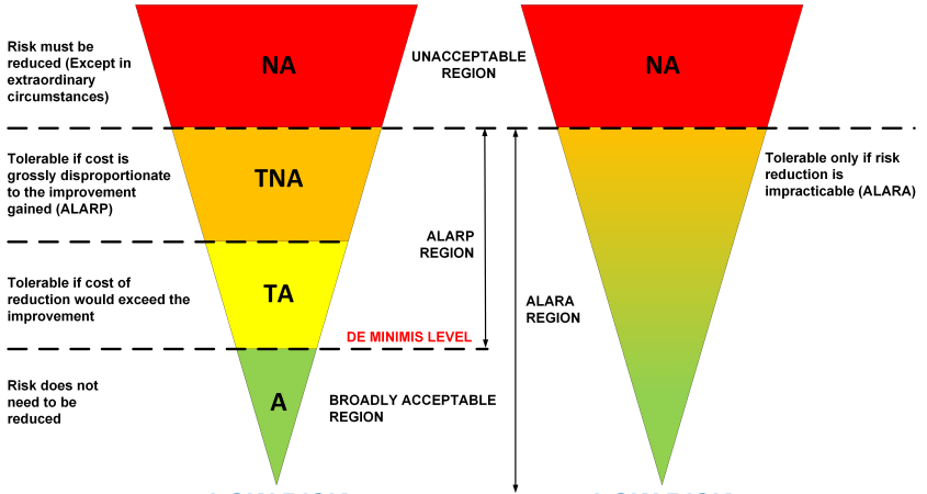


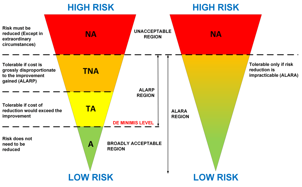


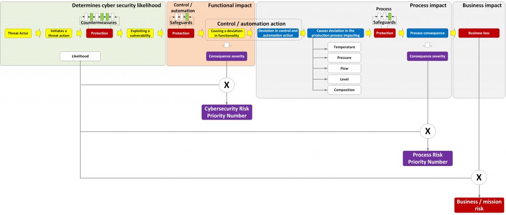


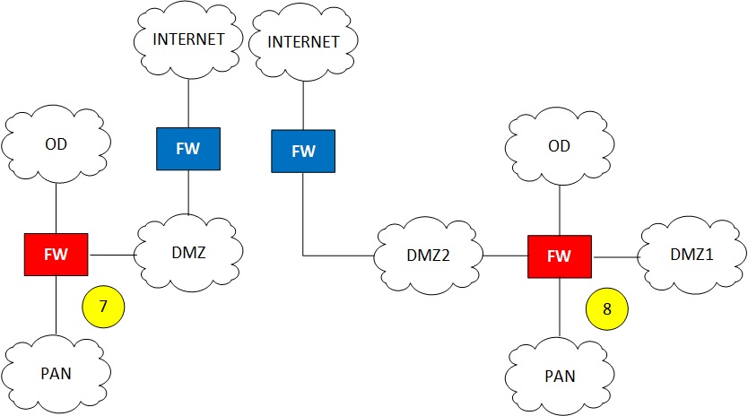

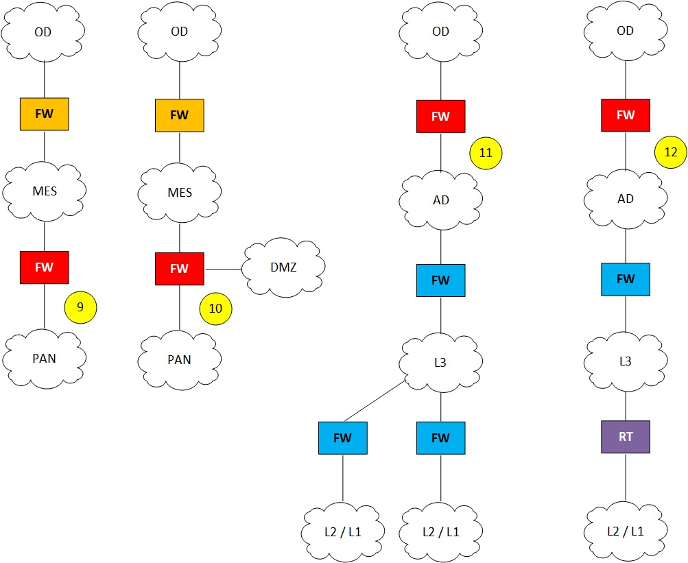


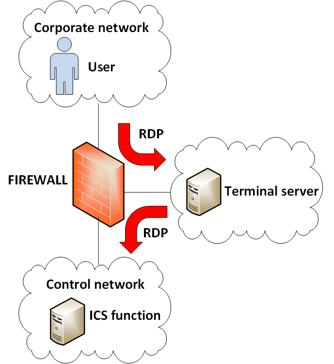


